0 electrical connection – Cleveland Motion Controls Classic Slim Cell Transducer REV AA User Manual
Page 6
INSTRUCTION NUMBER: AO-70165
6of 9
output signal of the transducer is positive. If the
force points to the “-“ the output is negative. This is
importance to know when wiring the transducer to
the amplifier, indicator, or controller terminals.
Interchanging the B (black wire) and C (red wire)
connections may be required in order to provide the
proper signal polarity for the device. (see Figure 6).
2.6
INSTALLATION PRECAUTIONS
To insure proper installation and operation of the
system, the following steps should be performed in
sequence. Failure to do so could seriously damaged
the Transducers and void the warranty:
- For SLIM CELLS that don’t have a through hole,
make sure that the shaft doesn’t go too deep inside
the Load Cell and touch the back plate (See
Figure 2 letter H).
- When mounting a roll with a shaft that comes
through the back plate (see Figure 4), push the
adapter to the inside of the SLIM CELL before
you tighten the set screws to allow for shaft
expansion.
- SLIM CELL installations having the roll and
SLIM CELL mounted on the inside of a machine
might require installing the roll and SLIM CELLS
as a unit.
2.7
SHAFT EXPANSION
- The SLIM CELL is design to accommodate shaft
expansion. The only precaution, as said in 2.6
INSTALLATION PRECAUTIONS, is that in
case of a shaft entering through the back plate of
the Load Cell (The two back plates facing each
other), you need to push the adapter toward the
front of the SLIM SPIN before you tighten the set
screws to allow for shaft expansion.
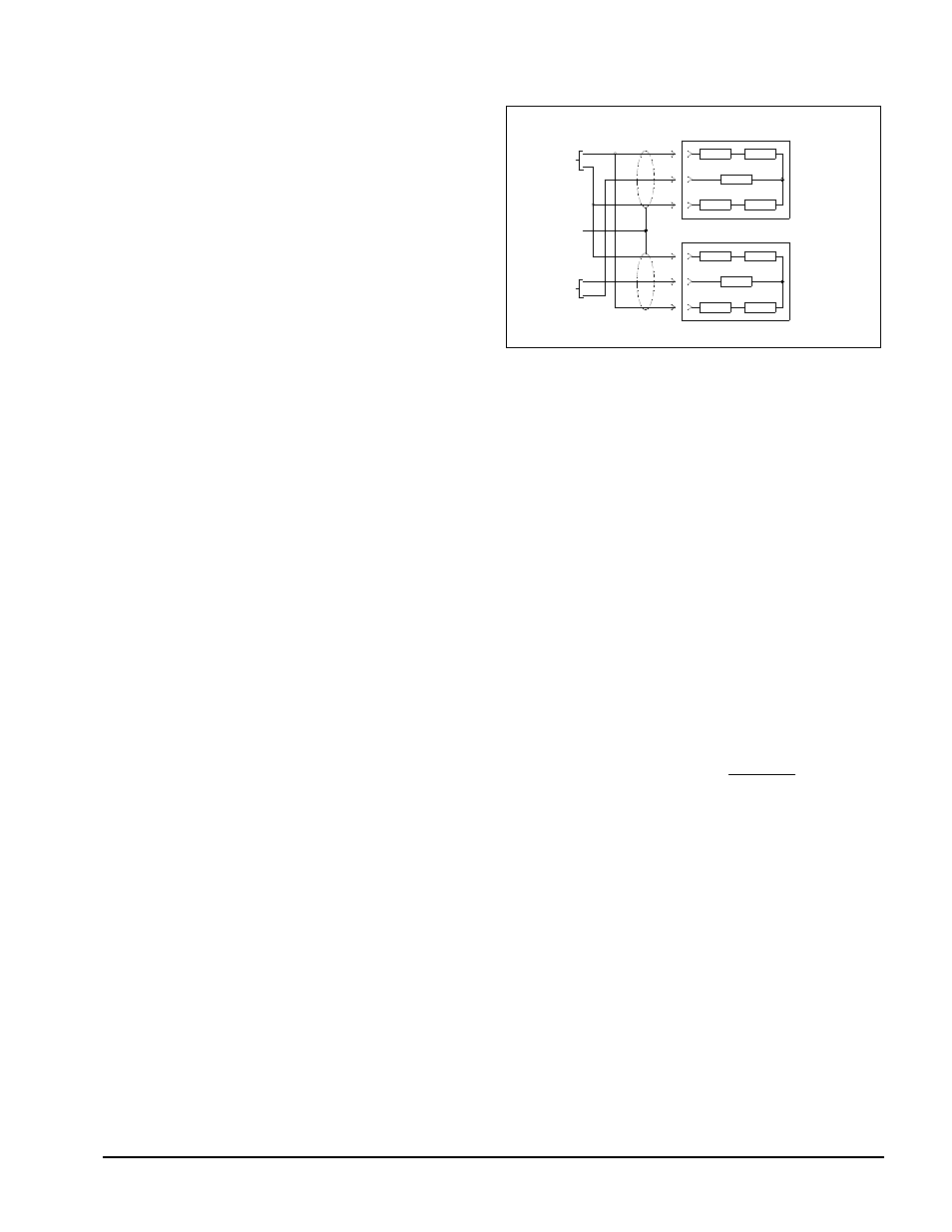
3.0
ELECTRICAL CONNECTION
Figure 6
Refer to the installation wiring diagrams supplied with
the Cleveland-Kidder tension indicator or controller
for making the transducer connections. Make certain
that the cables do not interfere with the web path and
that they are away from gearing or other moving parts.
Figure 6 is for reference only for use with a full bridge
transducer configuration. Many of the Cleveland-
Kidder indicators and controllers use only half bridge
transducer inputs and then sum the two transducers
signals internally. See the applicable installation
wiring diagrams for the tension indicator or controller.
3.1
MATING CONNECTORS FOR
TRANSDUCERS
CMC P/N
Mating Straight Connector,
Boot and Clamp Kit
MO-09854
Mating 90
Angle Connector,
Boot and Clamp Kit
MO-09855
3.2
INTRINSICALLY SAFE TRANSDUCERS
These transducers are intrinsically safe only when they
are part of a complete intrinsically safe system using
the TIX-1 tension indicator or wired per CMC control
drawings.
Barrier block assemblies and/or the individual barrier
blocks may be purchased from CMC. Please contact
CMC for part numbers and pricing.