0 installation, Figure 4 – Cleveland Motion Controls Classic Slim Cell Transducer REV AA User Manual
Page 4
INSTRUCTION NUMBER: AO-70165
4of 9
2.0 INSTALLATION
2.1 SELECTION OF TRANSDUCER
MOUNTING LOCATION
When selecting a transducer mounting location,
keep in mind that the tension-sensing roll must
NOT be mounted where the web wrap angle can
vary. Any change in the wrap angle will be sensed
by the transducers as a change in tension, and
indicated as such on the tension indicator.
Figure 3
In some cases, it may be impossible to find a
location for the transducers where the wrap angle
does not vary. The change in indicated tension that
will result can be calculated and, if small, may not
be significant.
2.2
MOUNTING SURFACE PREPARATION
The mounting surfaces for the transducers should
be flat and parallel. Prepare the machine frames or
mounting surfaces by removing any loose paint,
rust, scale, etc.
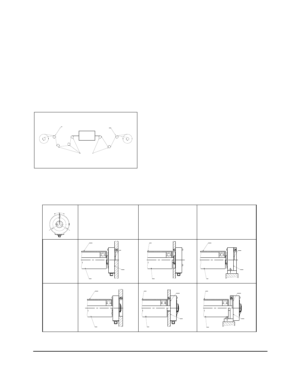
2.3 MOUNTING STYLE
The SLIM CELL Transducer is very versatile and
can be mounted in several mounting styles. If you
have not decided which style to use, evaluate which
is the most convenient, based on the machine
frame, ease of assembly and protection.
See Figure 4.
62 DEG OF ANGULAR ALIGMENT
WITH BOLT IN POSITION
WITH DEAD SHAFT
BP
FLUSH
WITH LIVE SHAFT
BF
HF
WITH LIVE SHAFT
WITH DEAD SHAFT
WITH DEAD SHAFT
WITH LIVE SHAFT
BF
WITH DEAD SHAFT
FLUSH
WITH LIVE SHAFT
HP
HF
WITH DEAD SHAFT
FL
USH
BP
BF
WITH DEAD SHAFT
FL
USH
H
P
H
F
WITH MOUNTING
BRACKET
OUTSIDE
FRAME
INSIDE
FRAME
BLANK BACK
PLATE
BACK PLATE
WITH HOLE
WITH ALIGNMENT
PILOT
WITH LIVE SHAFT
WITH AL
IGN
MENT
PILOT
WITH ALIGNMENT
PILOT
WITH LIVE SHAFT
WITH A
LI
GNMEN
T
PILOT
Figure 4