Figure 2 figure 1 – Cleveland Motion Controls Classic Slim Cell Transducer REV AA User Manual
Page 3
INSTRUCTION NUMBER: AO-70165
3of 9
B
C
E
G
D
H
I
M (BOLT DIA)
F
A
J
K
L
C
O
P
Q
R
S
T
U
V
W
X (BOLT DIA)
Y
N
SLIM CELL (ALONE)
MOUNTING BRACKET (WITH SLIM CELL)
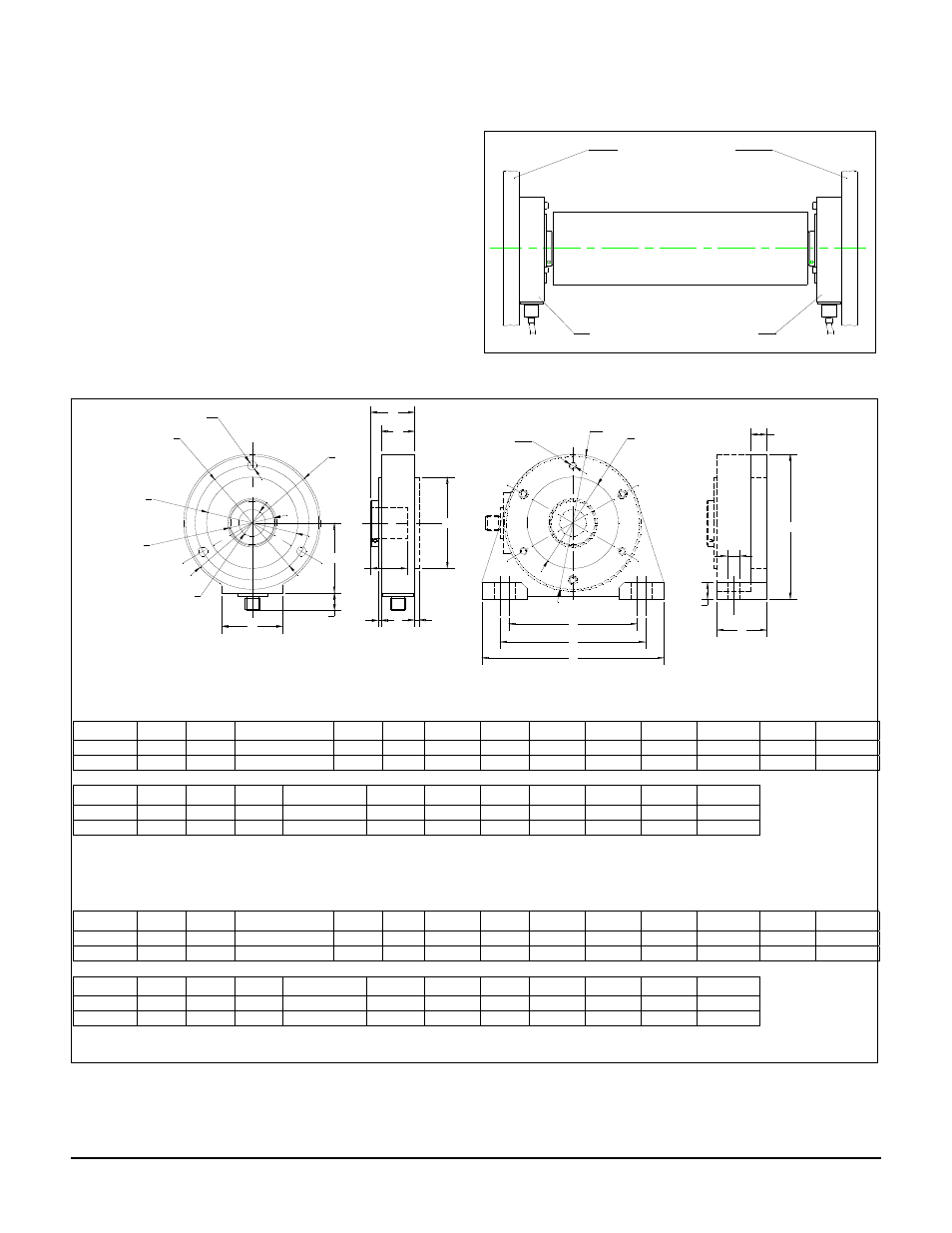
1.4 DESCRIPTION
The Cleveland-Kidder SLIM CELL transducers utilize
a sensing twin beam to which semiconductor strain
gages are bonded. With these high output signal gages
a very small force on the sensing beam will be shown
as a change in the tension signal.
For many applications SLIM CELL transducers are for use
with rotating (live) shaft rolls that are traditionally mounted
in Pillow Block Bearings. See Figure 1. For mounting
dimensions see Figure 2. But SLIM CELL transducers can
also be used with stationary (dead) shaft rollers.
Dimensions in inches, allow 2.5 in clearance for Connector
SIZE
A
B
C
D
E*
F
G
H
I
J
K
L
M
SLIM1
4.50
3.75
2.996-3.000
1.50
-
0.12
1.31
1.02
0.07
2.30
2.00
0.65
_ (3)
SLIM2
5.80
4.75
4.196-4.200
2.46
-
0.14
1.70
1.32
0.10
3.05
2.50
0.65
3/8 (3)
N
O
P
Q
R
S
T
U
V
W
X
Y**
1.02
4.22
4.78
6.00
3.000-3.006
4.50
0.55
0.55
1.60
4.75
3/8 (2)
_ (3)
1.36
5.50
6.5
8.00
4.200-4.206
5.80
0.65
0.65
2.00
6.2
_ (2)
3/8 (3)
*
See Table 3 for permissible Shaft Diameter. Bore Diameter is typically between Nominal Diameter+0.0007 and +0.0017 inch.
** Bolts supplied with bracket
Dimensions in mm, allow 64 mm in clearance for Connector
SIZE
A
B
C
D
E*
F
G
H
I
J
K
L
M
SLIM1
114.3
95.3
76.10-76.20
38.1
-
3.0
33.3
25.9
1.8
58.4
50.8
16.5
6mm (3)
SLIM2
174.3
120.7
106.58-106.68
62.5
-
3.6
43.2
33.5
2.5
77.5
63.5
16.5
8mm (3)
N
O
P
Q
R
S
T
U
V
W
X
Y**
25.9
107.2
121.4
152.4
76.20-76.35
114.3
14.0
14.0
40.6
120.6
10mm (2)
_ (3)
34.5
139.7
165.1
203.2 106.68-106.83
174.3
16.5
16.5
50.8
157.5
12mm (2)
3/8 (3)
*
See Table 3 for permissible Shaft Diameter. Bore Diameter is typically between Nominal Diameter+0.018 and +0.043 mm.
** Bolts supplied with bracket
Figure 2
Figure 1