Electrical connections and wiring, Mating connectors, Calibration – Cleveland Motion Controls ULTRA SERIES CARTRIDGE TRANSDUCER REV AA User Manual
Page 16: Lectrical, Onnections and, Iring, Ating, Onnectors, Alibration
U
LTRA
S
ERIES
S
TATIONARY
S
HAFT
T
RANSDUCER
MAN-70251
R
EV
.
AA
P
AGE
16
OF
18
3.6 E
LECTRICAL
C
ONNECTIONS AND
W
IRING
Refer to the installation wiring diagrams supplied with the Cleveland-Kidder tension indicator or controller for
making the transducer to amplifier connections. Make certain that:
• The cables do not interfere with the web path, and that they are away from gearing or other moving
parts.
• You exercise care when routing the cables to avoid pick-up from noise-radiating power cabling (motor
armature leads, AC main wiring, etc).
• In environments with severe electromagnetic noise, it may be necessary to route the cables inside
metallic conduit.
• Polarity changes are accommodated by reversing the orientation of the transducer or by interchanging
the black and white output wires.
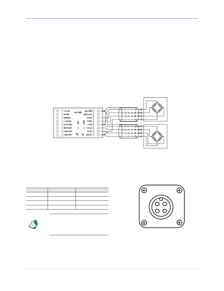
Figure 7 illustrates a typical full bridge transducer configuration.
LEFT XDCR
8
7
6
3
4
5
2
1
1
2
3
BLK
WHT
BLU
BRN
6
5
4
8
7
WHT
BLU
BLK
BRN
1
1
2
3
4
2
3
4
RIGHT XDCR
C
T
T
C
C
T
T
C
Figure 7 – Full Bridge Transducer Wiring
3.7 M
ATING
C
ONNECTORS
The M12 connector used on the Ultra Series Slim Cell transducer is a four-pin, DC keyed, male connector that mates
directly with the molded corsets offered by Cleveland Motion Controls. The following table lists the pin numbers
and cable colors that apply:
Pin Number
Wire Color
Signal
1 brown
Excitation
Voltage
2
white
Output - (low going)
3 blue
Excitation
Return
4
black
Output + (high going)
If you choose to make your own
cables or need to repair damaged
connectors, you can purchase a
separate mating connector from
Cleveland Motion Controls. To order,
use CMC part number, X44-34338.
Figure 8 - Front View of M12 Connector
1
2
3
4
When mating the connector, align the keying mechanism and pins so that they enter the socket without you having
to apply excessive force. Use your fingers to sufficiently tighten the coupling nut enough to ensure an adequate seal
and to discourage accidental loosening.
3.8 C
ALIBRATION
For the proper calibration procedure, refer to the Instruction Manual that accompanied your amplifier or tension
controller.