Installing the cartridge transducer, Mounting the transducer, Nstalling the – Cleveland Motion Controls ULTRA SERIES CARTRIDGE TRANSDUCER REV AA User Manual
Page 13: Artridge, Ransducer, Ounting the
MAN-70251
R
EV
.
AA
U
LTRA
S
ERIES
S
TATIONARY
S
HAFT
T
RANSDUCER
P
AGE
13
OF
18
3 I
NSTALLING THE
C
ARTRIDGE
T
RANSDUCER
The following sections provide you with detailed information and steps to correctly install the Ultra Series Cartridge
Transducer for use with stationary shafts.
3.1 M
OUNTING THE
T
RANSDUCER
The mounting surfaces for the transducer should be flat and parallel to each other. Remove any loose paint, rust or
scale from the machine frame before mounting.
Table F – Steps for Mounting an Ultra Series Transducer
If you are using this
type of Mounting
style:
Then, perform these steps:
Stud (S)
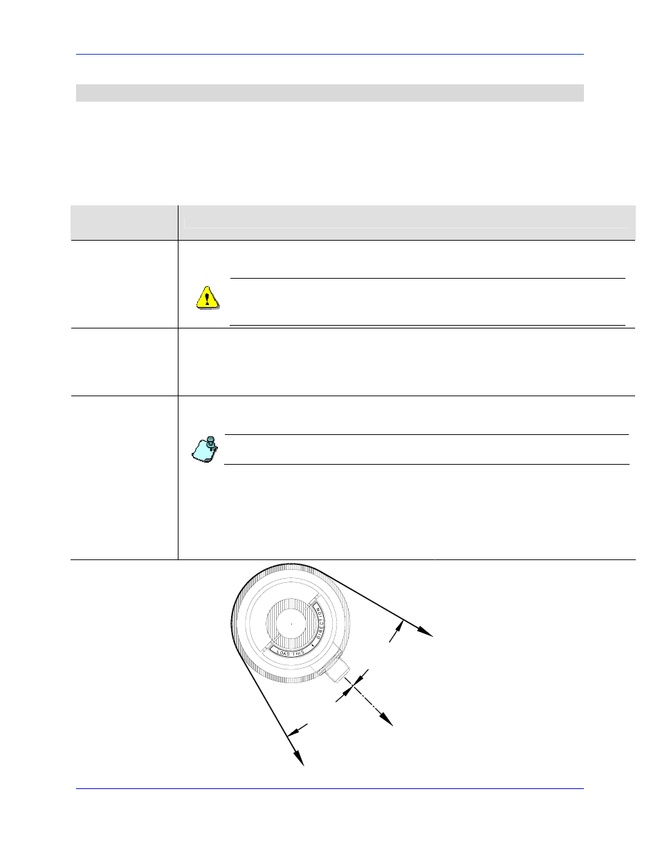
1. Before tightening the mounting bolt, rotate the transducer body until the force direction (indicated by the arrow
on the label) is aligned with the vector of the web force. The vector of the web force is the bisector of the wrap
angle.
Refer to
Rolls often have an uninterrupted shaft that extends to form the journals. Though the roll may be
described as having a “dead shaft”, neither journal end can rotate independently of the other.
Attempting to rotate one transducer, while the other end of the roll is clamped can result in damage
to the transducer.
Pillow Block and
Bearing Replacement
(PB, BR)
1. Loosely mount the transducer by lightly tightening the four (4) socket head cap screws that hold the lock plate to
the back of the transducer.
2. Rotate the body of the transducer body until the direction of the force (indicated by the arrow on the label) is
aligned with the vector of the web force.
3. Tighten the four (4) socket head cap screws to securely clamp the transducer in position.
Flange (F)
1. Before drilling the four (4) mounting holes, contemplate the orientation of the transducer taking into
consideration the location of the mounting screws. Be sure that the screws do not interfere with the position of
the connector. An optimal location for mounting holes also lets you maximize rotational alignment range.
Do not use the flange assembly as a drill template while not mounted to the transducer. The spacing
between flange halves is different when the transducer body is added.
2. Adjust the alignment of the transducer. First, be sure that the four (4) flange bolts are loose and then, loosen the
two (2) bolts that draw the flange halves together.
3. Rotate the body of the transducer body until the direction of the force, indicated by the arrow on the label, is
aligned with the vector of the web force.
4. Secure the flange to the transducer. Tighten the two (2) socket head cap screws that draw the flange halves
together.
5. Tighten the four (4) bolts that draw the flange to the mounting surface.
WRAP
ANGLE
BISCETOR
WRAP
ANGLE
BISECTOR
LOAD
DIRECTION
W
E
B
WE
B
Figure 5 - Proper Orientation of the Cartridge Transducer