Minimizing beam torque, Checking the transducer mounting, Inimizing – Cleveland Motion Controls ULTRA SERIES CARTRIDGE TRANSDUCER REV AA User Manual
Page 15: Orque, Hecking, Ransducer, Ounting
MAN-70251
R
EV
.
AA
U
LTRA
S
ERIES
S
TATIONARY
S
HAFT
T
RANSDUCER
P
AGE
15
OF
18
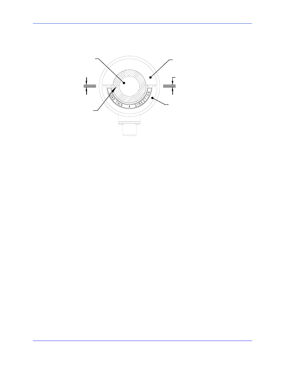
3. Tighten the shaft coupling cap. Be sure that the size of the gap on each side of the roll shaft is equal in width.
Refer to Figure 6.
EQUAL GAP ON BOTH SIDES
REMOVABLE CAP
STATIONARY HALF
OF SHAFT COUPLING
ROLL SHAFT
ALIGN BUSHING AND
CAP SPLITS
(DEAD)
Figure 6 - Correct Shaft Coupling Installation
3.4 M
INIMIZING
B
EAM
T
ORQUE
Rolls often have an uninterrupted shaft that extends to form the journals. Even though the roll may be described as
having a “dead shaft”, neither journal end can rotate independently of the other. Because of the twisting force,
attempting to rotate one transducer while the other end of the roll is firmly clamped can result in damage to the
transducer. Even though the force may not large enough to cause permanent damage, they can impair the accuracy
and stability of the transducer tension signal.
To minimize the potential for having accidentally stored a residual twisting force in the beams when the transducers
and roll were mounted, we recommend that you use the following steps to adjust and verify your transducer.
1. Slightly loosen the mounting bolts that secure one of the transducers to the machine frame so that the transducer
is free to rotate about the axis of the roll. Note that a small amount of rotation is possible using only moderate
force. At the outer diameter of the transducer housing, the rotation might amount to roughly 1/8” of
circumferential travel, as each transducer contributes just over two (2) mechanical degrees of rotational play.
2. Position the transducer at the approximate midway position before re-tightening the mounting screws. This
helps to ensure that the transducers shaft coupling is free to float rotationally. The residual torsional forces are
minimized on the beam assembly.
3. Lightly, twist the roll back-and-forth by hand to verify the amount of available free play. Approximately one or
two degrees angular free play should be evident.
3.5 C
HECKING
T
HE
T
RANSDUCER
M
OUNTING
Before preparing to apply force to the transducer(s) and calibrating the amplifier, inspect the load cell to confirm
that it is oriented and mounted in accordance to the installation instructions. Common problems include:
• Failure to mount transducers on flat (machined) surface.
• Poor shaft alignment that exceeds allowable limits.
• Fastener torque either excessive or insufficient.
• Transducer mis-oriented so that the axis of sensing is not true to the applied force vector (bisector of
the wrap angle).
• Roll is mounted without allowance for shaft expansion/contraction at shaft coupling.
• The transducer is positioned in the web path so that the wrap angel is not constant.