Hach-Lange POLYMETRON 9500 Conductivity Module User Manual User Manual
Page 16
5. Disconnect the sensor from the sensor cable and push enter. Connect a 50 kΩ, 5 kΩ, 500 Ω, or
50 Ω NIST resistor (accuracy ±0.05%) on pins 2-3 of the sensor cable and push enter. Use the
arrow keys to enter the value of the resistor and push enter.
6. Review the calibration result:
• PASS—the calibration is successful.
• FAIL—the cell constant is outside of accepted limits. Clean the sensor and retry. Refer to
on page 18 for more information.
7. If the calibration passed, push enter to continue.
8. If the option for operator ID is set to YES in the CAL OPTIONS menu, enter an operator ID. Refer
on page 17.
9. On the NEW SENSOR screen, select whether the sensor is new:
Option Description
YES
The sensor was not calibrated previously with this controller. The days of operation and previous
calibration curves for the sensor are reset.
NO
The sensor was calibrated previously with this controller.
10. Reconnect the sensor, return it to the process and push enter. The output signal returns to the
active state and the measured sample value is shown on the measure screen.
Note: If the output mode is set to hold or transfer, select the delay time when the outputs return to the active
state.
Resistor calibration (inductive conductivity sensors)
This type of calibration is sometimes referred to as an electrical calibration and is used to verify the
electrical connection rather than the sensor itself.
1. Push the menu key and select SENSOR SETUP>[Select Sensor]>CALIBRATE.
2. If the pass code is enabled in the security menu for the controller, enter the pass code.
3. Select RESISTOR CAL and push enter.
4. Select the option for the output signal during calibration:
Option
Description
ACTIVE
The instrument sends the current measured output value during the calibration procedure.
HOLD
The sensor output value is held at the current measured value during the calibration procedure.
TRANSFER A preset output value is sent during calibration. Refer to the controller user manual to change
the preset value.
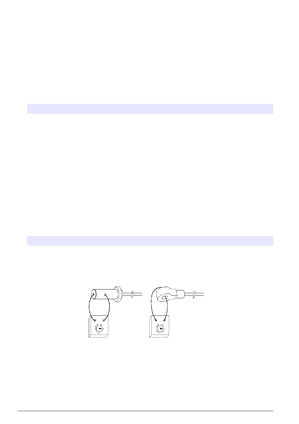
5.
Remove the sensor from the sample. Place a 5 kΩ, 500 Ω, 50 Ω, or 5 Ω resistor loop through the
sensor and push enter. Push enter when the displayed resistor value is stable. Use the arrow
keys to enter the actual value of the resistor and push enter.
6. Review the calibration result:
• PASS—the calibration is successful.
• FAIL—the calibration slope or offset is outside of accepted limits. Clean the sensor and retry.
Refer to
on page 18 for more information.
16 English