Installation – Hach-Lange CL17 USER MANUAL User Manual
Page 19
17
Installation
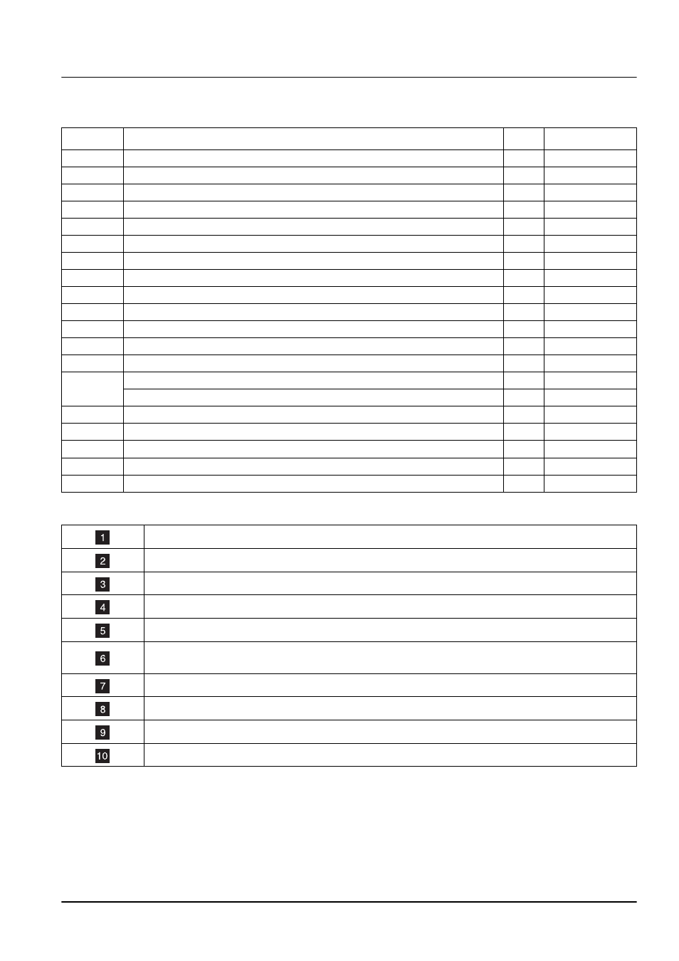
Table 1 Sample Conditioning Parts List (refer to
Item Description
Qty
Catalog
Number
1
Clamp, Conduit Hanger, 1-inch
4
47349-00
2
Coupling, 1-inch, SCH 40, PVC pipe
1
54175-00
3
Coupling, ½-inch FPT x ½ FPT PVC
1
54176-00
4
Fitting, Reduce Bushing, PVC, Hex
2
23002-00
5
Fitting, Stem Adapter, ½-inch O.D., ¼ NPT
1
54180-00
6
Fitting, Tee, 1-inch x 1-inch
1
46622-00
7
Fitting, Tube, Connector, Male (¼-inch tubing)
3
51246-00
8
Fitting, Tube, Connector, Male (½-inch tubing)
2
51262-00
9
Fitting, Tube, ½-inch O.D. x ½-inch Male NPT
1
54178-00
10
Fitting, Tube, ½-inch O.D. Union Elbow
1
54179-00
11
Fitting, Tube, ½-inch O.D., Union Straight
1
54181-00
12
Pipe, Pre-cut Drain, 1-inch Diameter, PVC
1
51239-00
13
Pipe, Drain, Clear
1
54174-00
14
Strainer, Y-body
1
54183-00
Filter, 40-mesh Screen (provided with strainer and in Maintenance Kit, 55165-00)
1
54184-00
15
Teflon
®
, Thread Tape, ¼-inch wide
1
70608-24
16
Tubing, Polyethylene, 0.250 O.D., 0.040 W, Black
15 feet
30616-00
17
Tubing, Polyethylene, 0.500 O.D., 0.062 W, Black
10 feet
51159-00
18
Valve, Ball, PVC, ½ NPT, PVC
1
54177-00
19
Valve, Ball, PVC, ¼ NPT, PVC
1
51395-00
Table 2Sample condition kit parts list notes for
The filter element is factory installed. A spare filter is provided in the Maintenance Kit.
Use PVC pipe cement to assemble. Leave pipe open to the atmosphere.
This the “Low Flow” option.
This the “High Flow” option.
The
1
/
2
inch drain tube must have an air-break. (Must be supplied by the customer.)
Use the Unfiltered Sample Bypass to return to system under zero pressure, if possible, or to drain.
Use customer supplied PVC pipe as required to run to drain location.
Install the Sample Flow Regulator (Constant Head Device) 24 inches above the instrument.
Air Gap
Drain
Use either 7 and 16 or 8 and 17.