Cashco Ranger QCT User Manual
Page 11
IOM-Ranger
11
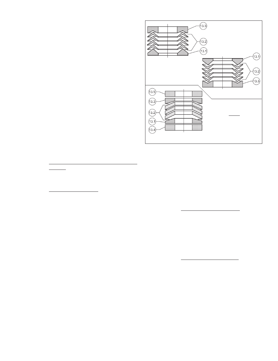
Standard TFE
V-ring Packing Stack
Opt-38HT High Temp.
Packing Stack
Opt-38V Vaccum Service
V-ring Packing Stack,
For 1", 1-1/2" & 2" body
sizes use ONLY 2 packing
rings (13.2)
For 3", 4", 6" & 8" body
sizes use 3 packing rings
(13.2)
FIGURE 11
Packing Stack Orientation
Push down on the packing follower (15)
using fi ngers; all V-rings (13.2) and upper
adapter (13.3) should easily slide into the
body (1) stuffi ng box.
NOTE: It will be necessary to pull up on
the stem (7) as the adapters (13.1, 13.3)
and packing rings (13.2) are “pushed” into
the stuffi ng box.
f. For body sizes 1", 1-1/2" & 2":
f.1. Slide both yoke (12) and packing
fl ange (14) over end of stem (7), prop-
er ly ori ent ed, and over pack ing studs
(21). Align matchmarks be tween body
(1) and yoke (12).
f.2. Install two cap screws (19) to as-
sem ble the yoke (12) to the body (1)
securely.
g. For body sizes 3", 4", 6" & 8":
g.1. Slide yoke (12) over end of stem (7),
properly oriented, and over packing
studs (21). Align matchmarks be-
tween body (1) and yoke (12).
g.2. Slide packing fl ange (14) over end of
stem (7), properly oriented, and over
pack ing studs (21).
g.3. Install two nuts (22) on studs (20) to
assemble the yoke (12) to the body
(1) securely.
h. Proceed to Article 6 for Opt-38 Jammed
Pack ing.
5. Proceed to Subsection G. for installation of
pack ing (13).
F. Stem Reassembly – Trim Removed from Body
1. Install retainer sleeve subassembly (8) and
stem subassembly (7) in ac cor dance with
Subsection E, Ar ti cles 1 through 3, pre vi ous.
Rotate stem (7) to plug's (6) closed po si-
tion.
2. Install trim in accordance with Subsection C,
Ar ti cles 1 through 10, previous.
3. Install packing in accordance with Sub-
section
G.
G. Packing Replacement:
Remove stem as per Subsection D. previous and
pro ceed as follows.
1. Secure body (1) in a vise with stem (7) verti-
cal to the fl oor. Reassemble stem (7) per
ap pro pri ate Subsection E., F., or H.
2. Never replace packing (13) without re con-
di tion ing the stem (7) surface fi nish and the
body (1) stuffi ng box as specifi ed in Sub sec tion
IV.D.
3. For TFE V-Ring Packing. (See Figure 11.)
NOTE: Following text pertains to “stan dard”
pack ing stack (13) orientation. Stack procedures
differ slightly for other packing options. See Fig-
ure 11.
a. Remove packing follower bushing strip
(16). Solvent clean packing follower (15).
Insert new packing follower bushing strip
(16). Ensure no overlap of strip (16).
b. Carefully place lower adapter (13.1) of
packing ring set (13) over stem's (7) end,
properly oriented (see Figure 11). Using
the packing follower (15), push the adapt er
(13.1) into the body's (1) stuffi ng box.
c. Carefully
install
the
fi rst individual V-ring
(13.2) over stem's (7) end, properly ori-
ent ed. Push down as far as possible using
fi n gers. Carefully place each ring (13.2)
upon the other until all V-rings (13.2) are
stacked, properly oriented.
d. Place upper adapter ring (13.3) over the
stem's (7) end, properly oriented.
e. Place the packing follower (15) over the
stem (7) end, properly oriented, until
sit ting on the upper adapter ring (13.3).