Caution – Cashco Ranger QCT User Manual
Page 10
IOM-Ranger
10
4. For Non-Live-Loaded Packing Con struc tion:
a. Remove two packing flange stud nuts
(22) and two cap screws (19) on the 1",
1-1/2" and 2" sizes, or four nuts (22) on the
3", 4", 6" and 8" sizes.
b. Pull yoke (12), packing fl ange (14), pack ing
follower (15) and follower bushing strip (16) off
over end of stem (7). Re place packing follower
(15) if sig nifi cant ly cor rod ed. Always replace
fol low er bushing strip (16) when of standard
construction.
c. Proceed with previous steps 3.j. through 3.q.
for stem removal.
E. Stem Reassembly – Trim Retained in Body:
1. Slide retainer sleeve subassembly (8) onto
the stem subassembly (7), with the car bon
bushing (8.2) end against the shoul der of the
stem subassembly (7).
NOTE: For Slurry Trim see Subsection H.
2. Insert the stem/retainer sleeve (7)(8) as sem-
bly into the body (1), aligning the hole in the
retainer sleeve (8) to be directly in line with
the thread ed hole in the body (1) bonnet.
Align the stem sub as sem bly (7) so that the
plug’s (6) tongue and the stem's (7) groove
will engage.
NOTE: A small "fl at" area has been milled on the
stem and for correct engagement this "fl at" must
be on the same side as the face of the plug (6).
3. Visually
confi rm alignment of hole in re tain er
sleeve (8.1) with threaded hole in body (1)
bonnet. Place thread sealant Cotronic Res-
bond 907, or equal, on stem retainer screw
(17) threads for valves used in non-oxygen
service; thread sealant to be Oc ci den tal
Petroleum Corp. Fluorolube GR-362, or
equal, for valves used in oxygen service.
Insert and tight en stem re tain er screw (17)
20-25 ft# (27-34 N-M) for 1"– 2" sizes,
80-85 ft# (108-115 N-M) for 3"– 8LF" sizes
and 90 ft# (122 N-M) for 8"HF size.
4. Rotate stem (7) to ensure tongue and groove
engagement with plug (6).
m. Using a suitable solvent acceptable to the owner,
thoroughly clean the valve stem (7) and the
body's (1) stuffi ng box. Inspect surface fi nish of
stem sub as sem bly (7) and internal wall fi nish of
packing box bore at packing (13) area. If deeply
scratched, corroded or pit ted, re place with new
parts.
n. It will be desirable to restore the surface of
the body's (1) stuffi ng box to 16 mi cro-inch Ra
fi nish; metal removal should not exceed 0.001
inch ma te ri al.
o. It will be desirable to restore the sur face of the
stem's (7) critical area to 6–8 micro-inch Ra fi n-
ish or better, metal re mov al should not exceed
0.001 inch ma te ri al. Minimum stem OD should
not be less than indicated in Table 4.
p. Remove retainer sleeve sub as sem bly (8) from
stem subassembly (7). Ex am ine carbon bush-
ing insert of re tain er sleeve subassembly (8)
for dam age or signs of wear. Replace re tain er
sleeve sub as sem bly (8) if worn more than 0.005
inch (0.13 mm). See Figure 12 for indicated
di men sion “X”.
q. Examine packing studs (21) and nuts (22).
Replace if signs of corrosion are present.
TABLE 4 - STEM O.D.
Body Size
Minimum Stem O.D.
1", 1-1/2" & 2"
(DN25, 40 & 50)
.620
3" & 4"
(DN80, 100)
.995
6" & 8"
(DN150, 200)
.995
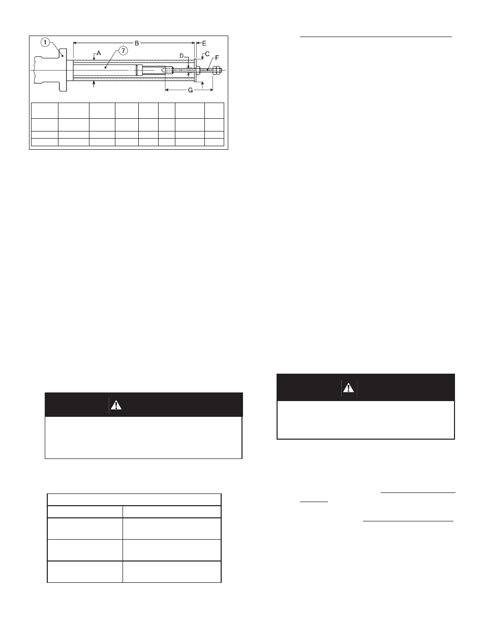
DIMENSIONS
Valve
A
B
C
D
E
F
G
Size
(Pipe Size)
(O.D.) (I.D.)
(Thd Rod)
1", 1-1/2,"
3/4"
7-13/16" 1-1/4" 5/16" 3/16" 1/4"-28
4"
2"
3",
4"
1-1/2" 11-13/16" 2-1/8" 7/16" 1/4" 3/8"-24 4-1/2"
6",
8" 2-1/2" 9-3/16" 3-1/8" 7/16" 1/4" 3/8"-24 4-1/2"
FIGURE 10: Stem Puller
CAUTION
Do not hammer on end of stem. Potential exists to
cause damage to the tongue and groove connection
or to the seals.
CAUTION
The tongue and groove connection between the stem
subassembly (7) and the plug (6) can cause me chan i cal
damage or disengagement if the carbon bushing in sert
is worn.