Installation instructions, Figure 2 figure a, Figure b – Hydrotech 2510 AIO SXT Chemical Free Iron Filter Operation Manual User Manual
Page 8
Installation Instructions
All government codes and regulations governing the installation of these devices must be observed.
CAUTION: If the ground from the electrical panel or breaker box to the
water meter or underground copper pipe is tied to the copper water lines
and these lines are cut during installation of the Noryl bypass valve and/
or poly pipe, an approved grounding strap must be used between the
two lines that have been cut in order to maintain continuity. The length of
the grounding strap will depend upon the number of units being installed
and/or the amount of copper pipe being replaced with poly. See Figure
A & B.
In all cases where metal pipe was originally used and is later interrupted
by poly pipe or the Noryl bypass valve as in Figure B or by physical
separation as in Figure A, an approved ground clamp with no less than
#6 copper conductor must be used for continuity, to maintain proper
metallic pipe bonding.
Check your local electrical code for the correct clamp and cable size.
1. Determine the best location for your water softener, bearing in mind
the location of your water supply lines, drain line and 120 volt AC
electrical outlet. Subjecting the softener to freezing or temperatures
above 110°F (43°C) will void the warranty.
2. Shut off all water at main supply. On a private well system turn off
power to pump and drain pressure tank. Make certain pressure is
relieved from complete system by opening nearest faucet to drain
system. Shut off fuel supply to water heater.
Media Installation (When Necessary)
•
Remove the valve from the mineral tank.
•
Temporarily plug the open end of the riser tube to ensure that no resin or gravel falls down into the distribution.
•
Fill mineral tank one quarter full of water to protect distribution during gravel installation.
•
Slowly and carefully add the gravel support bed and the softener media leveling each layer as it is placed into the tank.
•
Unplug the riser tube, carefully position the valve over it and turn the valve into the threads in the fiberglass tank, tightening
securely into tank. Note: Ensure that the internal O-ring in the valve fits securely over the riser tube. Silicone grease (#13691)
or other food grade lubricant may be applied to the O-ring to ease installation of the riser tube. DO NOT use petroleum based
lubricants as they will cause swelling of 0-rings and seals.
•
The filter is now charged with filter resin.
•
It is recommended that the filter tank now be completely filled with water (SLOWLY) to soak the resin before startup. This will
allow the media to absorb water as well as help displace any trapped air. This will reduce the chance of backwashing resin out
during startup.
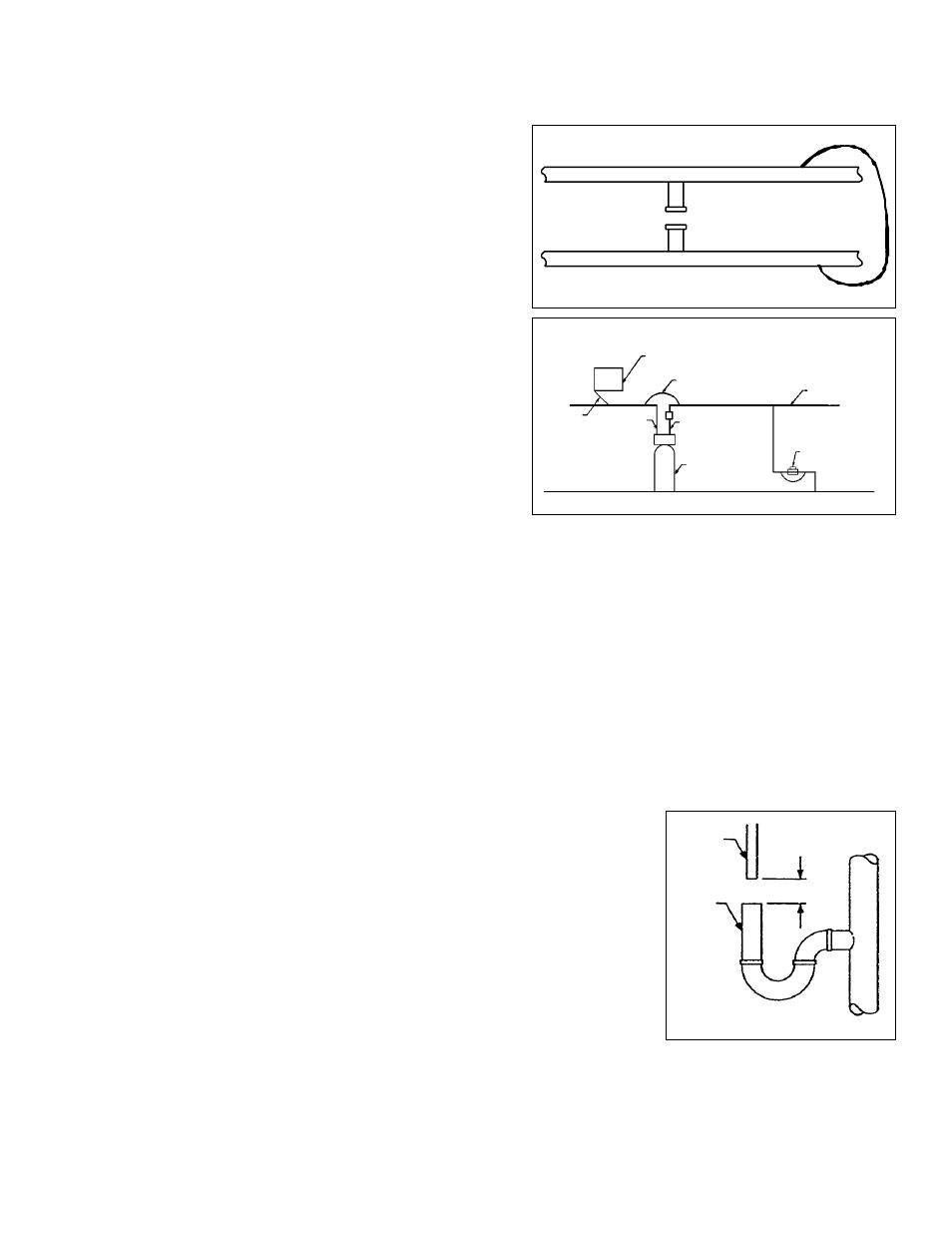
3. Install check valve before the inlet of the valve.
4. Cut main supply line as required to fit plumbing to control valve.
5. Solder or solvent weld plumbing. Do not apply heat to any fitting connected to control
valve as damage may result to internal parts. Check to be certain water supply pipe is
connected to control valve inlet fitting, and pipe connected to control valve outlet fitting is
in direction of house service (see Figure 2).
6. Remove the retaining clip and pull out drain line flow control assembly from valve body.
Unscrew drain line fitting elbow from drain line flow control. Apply pipe dope or teflon tape
to threads. Reassemble to valve body, making certain drain line flow control assembly is
fully inserted into valve body before installing the clip. Attach 1/2 inch ID drain line to drain
elbow.
7. Position drain hose over drain and secure firmly. To prevent back-siphoning of sewer
water, provide an air gap to code or equivalent. (Figure 2) Do not raise drain hose more
than 10 ft. above floor.
8. During initial backwashings, a small amount of fine white media may be observed in the drain water. This is normal. Now supply
power to timer and allow the unit to finish the cycle on its own. For next-Sand media, please follow the start-up instructions on
the next page.
9. Set time-of-day and backwash frequency (see Section 6, Programming Backwash Controls).
NOTE: After start-up, this unit may take several days to completely remove the iron. This is normal because of the nature of the
media.
6
EQUIPMENT
DRAIN LINE
AIR GAP
DRAIN
2”
Figure 2
Figure A
Electrical Panel
Ground Strap
Poly Pipe
Check Valve
Ground
From
Panel
Poly Pipe
Filter
c/w Bypass
Copper Pipe
Water Meter
Outside Water Line For Outside & 3rd Tap Comes From Meter
Filtered Water Line in Home
Unfiltered Water Bypass
Loop Cut & Capped
Ground Strap Required
Because of Break in Continuity
Figure B