Gardner Bender SPR300+ AC Snap-Around Volt-Ohm-Ammeter User Manual
Page 2
(2) Set the range switch to the highest Vac range position.
(3) Connect the test leads to the circuit under test (Fig.4) and read the voltage
directly on the scale.
(4) When the reading is less than one half of the scale set the range switch to the
next lower range position. For maximum accuracy, select the lowest range
possible without overranging the meter.
4.4) RESISTANCE MEASUREMENTS
WARNING !
Attempting resistance measurements on live circuits can cause electrical
shock, damage to the instrument and damage to the equipment under
test. Resistance measurements must be made on de-energized (DEAD)
circuits only for maximum personal safety. The fuse protection installed
in this instrument will reduce the possibility of damage to the instrument
but not necessarily avoid all damage or shock hazard.
Never jump out the protective fuse. Replace the fuse with AWS Part #F-1 or approved
equal. Only use fuses that are quick acting and have high current interrupting capacities.
(1) Teat the circuit to make sure it is de-energized. Refer to section 4.3 on how
to test for voltage.
(2) Set the range switch to the ohm range position. Insert the red test lead into
the “OHM” terminal and black test lead into the “COM” terminal (Fig.5).
(3) With the test leads open set the pointer over the “∞”(infinity)mark at the left
end of the ohm scale, using the zero adjust screw.
(4) With the test leads shorted set the pointer over the “0”mark at the right end
of the ohm scale, using the ohm zero adjust knob (Fig.6).
Note : When this adjustment does not bring the pointer over the “0”mark replace the
battery.
(5) Connect the test leads to the circuit under test (Fig.7) and read the resistance
directly on the scale.
Insulation Protection : 10MΩ min. at 1000 V between electrical circuit and
housing or metal section of transformer jaws.
Overload Protection : AWS Part #F-1,0.5A, 250V, 1/4"×1-1/4" fuse and
diode
Frequency Response : 50-400Hz
Conductor Size :
Approx. 1.2"(30mm)
Dimensions :
8.7"(L)×3.3"(W)×1.6"(D)
220mm (L) ×83mm (W) ×40mm (D)
Weight :
Approx. 13.8 oz. (390g) battery included
Power Source :
One 1.5V AA size battery, AWS Part #B-1
Fuse :
1/4"×1-1/4", .5A, 250V FF AWS Part #F-1
Temperature :
5℃ to 40℃ Max RH 80% to 31℃, decreasing
linearly to 50% RH at 40℃
Cleaning :
Wipe with a clean dry cloth.
Accessories : (included) Test Leads Model TL-52 one alligator, one with prod.
Banana Plugs are shrouded, Battery B-1, AA type 1.5V.
Two 0.5/250V Fuses F-1 (spare fuse included),
durable Case C-53.
(optional) Energizer Model E-1, AG-940, TL-5, TL-5-A1, TL6,
TL6-A1, TL-39, TL-42, TL-44, TL-48, TL-49 and
C-53A Carrying Case.
Instrument complies with insulation category (Overvoltage Category ll). Pollution
Degree 2 in accordance with IEC-664. Indoor use.
If the equipment is used in a manner not specified, the protection provided by
the equipment may be impaired.
3) SAFETY PRECAUTIONS
The following safety precautions must be observed to insure maximum personal
safety during the operation, service and repair of this meter :
1. Read these operating instructions thoroughly and completely before
operating your meter. Pay particular attention to WARNINGS which will
inform you of potentially dangerous procedures. The instruction in these
warnings must be followed.
2. Always inspect your meter, test leads and accessories for any sign of
damage or abnormality before every use. If any abnormal conditions exist
(eg. broken test leads, cracked cases, etc.), do not attempt to take any
measurements. Refer to Return for Repair section.
3. Do not expose the instrument to direct sunlight, extreme temperature or moisture.
4. Never ground yourself when taking electrical measurements. Do not touch
exposed metal pipes, outlets, fixtures, etc., which might be at ground
potential. Keep your body isolated from ground by using dry clothing, rubber
shoes, rubber mats, or any approved insulating material.
5. To avoid electric shock use CAUTION when working with Voltages above 40
Vdc or 20 Vac. Such voltages pose a shock hazard.
6. Never exceed the maximum allowable input value of any function when taking
a measurement. Refer to the specifications on page 1 for maximum inputs.
7. Never touch exposed wiring, connections or any live circuit when attempting
to take measurements.
8. Do not attempt to operate this instrument in an explosive atmosphere (i. e.
in the presence of flammable gases or fumes, vapor or dust).
9. When testing for the presence of voltage, make sure the voltage function is
operating properly by reading a known voltage in that function before
assuming that a zero reading indicates a no-voltage condition. Always test
your meter before and after taking measurements on a known live circuit.
10. Calibration and repair of any instrument should only be performed by
qualified and trained service technicians.
11. Do not attempt calibration or service unless trained and another person,
capable of rendering first-aid and resuscitation, is present.
12. Do not install substitute parts or perform any unauthorized modification of
the instrument. Return the instrument to Sperry Instruments, Inc. for service
and repair to insure that safety features are maintained.
4) OPERATION
BEFORE PROCEEDING WITH ANY MEASUREMENT, READ THE SAFETY
PRECAUTIONS SECTION 3.
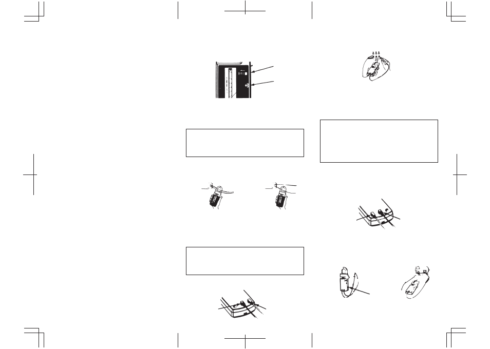
4.1) PREPARATION
(1) To ensure greatest accuracy, the pointer should be set exactly to the zero
position by rotating the zero adjust screw (Fig 1).
(2) Make certain that the pointer lock button is in the open position (Fig. 1).
4.2) AC CURRENT MEASUREMENTS
WARNING !
This instrument is designed to take current readings on circuits with a
maximum voltage above ground not exceeding 600 Vac. Using it on
circuits above 600 Vac poses a shock hazard to the user.
(1) Set the range switch to the highest 150 Aac range position.
(2) Press the trigger to open the transformer jaws and clamp onto one conductor
only (Fig. 2). Read the current directly on the scale. It is recommended that the
conductor be placed at the center of the closed jaws for maximum accuracy.
(3) When the reading is less than one third of the scale set the range switch to
the next lower range position. For maximum accuracy, select the lowest
range possible without overranging the meter.
4.3) AC VOLTAGE MEASUREMENTS
WARNING !
This instrument is designed to take voltage readings up to a maximum
of 600 Vac. The “COM”terminal voltage should not exceed 500 V
measured to ground potential. Do not exceed these maximums.
(1) Insert the red test lead into the “VOLT”terminal of the instrument and the
black test lead into the “COM” terminal (Fig.3).
Pointer Lock
Zero Adjust
Wrong
Correct
Volt
Com
Fig.1
Fig.2
Fig.3
Fig.4
Fig.5
Fig.6
Fig.7
Com
Ohm
Ohm Zero
Adj. Knob