A) (b) (c) (d) – Gardner Bender CP80 Floor Mount Assembly User Manual
Page 2
WARRANTY: GB ELECTRICAL, INC. warrants its
products against defects in workmanship and
materials for 1 year from date of delivery to user.
Chain is not warranted. Warranty does not cover
ordinary wear and tear, abuse, misuse, overloading,
altered products or use of improper fluid.
WARRANTY RETURN PROCEDURE: When question
of warranty claim arises, send the unit to the nearest
GB Authorized Service Center for inspection,
transportation prepaid. Furnish evidence of purchase
date. If the claim comes under the terms of our
warranty the Authorized Service Center will REPAIR
OR REPLACE PARTS AFFECTED and return the unit
prepaid.
PARTS AND SERVICE: For quality workmanship and
genuine GB ELECTRICAL parts, select an Authorized
GB Service Center for your repair needs. Only
repairs performed by an Authorized Service Center
displaying the official GB Authorized sign are backed
with full factory warranty. Contact GB Electrical
(414) 352-4160 for the name of the nearest GB
Authorized Service Center.
REPAIR AND SERVICE INSTRUCTIONS: For repair service and parts contact your nearest GB ELECTRICAL
Service Center. The Service Center will provide complete and prompt service on all GB ELECTRICAL products.
GB Electrical, Inc.
An Applied Power Company
6101 N. Baker Road, Milwaukee, WI 53209
Phone: (414) 352-4160
FAX (414) 352-2377
RPS-0132 Rev. A
03/07
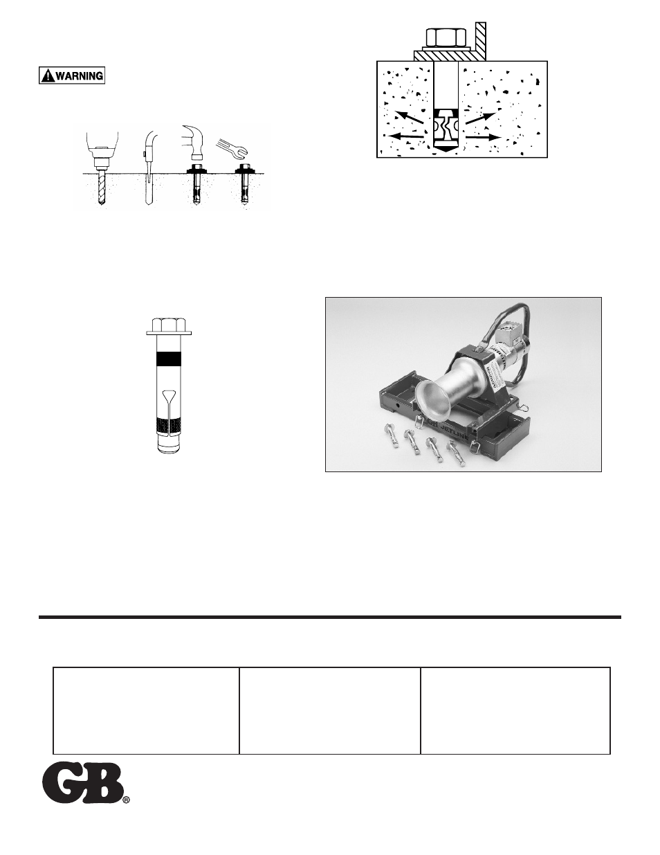
b. Clean holes using compressed air and a wire brush.
Check the hole depth and adjust as necessary.
See figure 3(b).
Wear Safety Goggles
4. Position the mounting base over the drilled holes.
Assemble anchor with nut and washer so that the top
of the nut is flush with the top of the anchor.
See figure 4.
5. Insert the anchors through the four holes in
the mounting base and into the drilled holes in
the concrete. Drive the anchors into the holes
until the washer is flush with the mounting base.
See figure 5.
6. Tighten the anchor nuts 3-5 turns past the hand tight
position or until all four anchors securely hold the
mounting base to the concrete.
7. Position the CP800 Power Head on the mounting
base. See figure 6. Insert the two long pins through the
outside of the base into the Power Head frame and
exiting the other side of the mounting base. Insert an
“R” clip into the hole of each pin.
Figure 3
Figure 5
Figure 6
Figure 4
(a)
(b)
(c)
(d)