Gardner Bender B2000 Series J Cyclone Bender User Manual
Page 2
CAUTION: Do not attempt to bend conduit or pipe
other than
1
⁄
2
" through 2" IMC, EMT, rigid steel or
aluminum. Bending other materials will damage the
bender and void the warranty.
NOTE: All operations referring to “toward the operator”
are viewed from the lifting handle end of the bender frame.
3.0 SPECIFICATIONS
Power Source .....................................120 V 60 cycle AC
Pendant Control Circuit ......................12 VDC
Motor ..................................................1 HP 100 V 60 cycle DC
Weight ................................................408 lbs.
Height .................................................38 inches
Width ..................................................31 inches
Length.................................................45 inches
Circuit Breaker....................................15 Amp
Bend Capability ..................................
1
⁄
2
" - 2" IMC, EMT
Rigid Steel or
Rigid Aluminum
4.0 OPERATION
4.1 Bending
1
⁄
2
",
3
⁄
4
" and 1" IMC, EMT and
rigid conduit:
1.
Position the bender in a level dry area large enough to
permit loading and unloading various lengths of conduit.
Position the frame, either horizontally or vertically, by
pulling the spring loaded pin on the side of the bender
frame. See Figure 2.
Figure 2. Vertical Position
2.
Identify the type (IMC, EMT or Rigid) and size conduit to
be bent.
3.
Locate the markings that indicate which grooves are used
for specific materials, and which grooves are used for
specific size conduit. See Figure 3.
Figure 3. Set Up
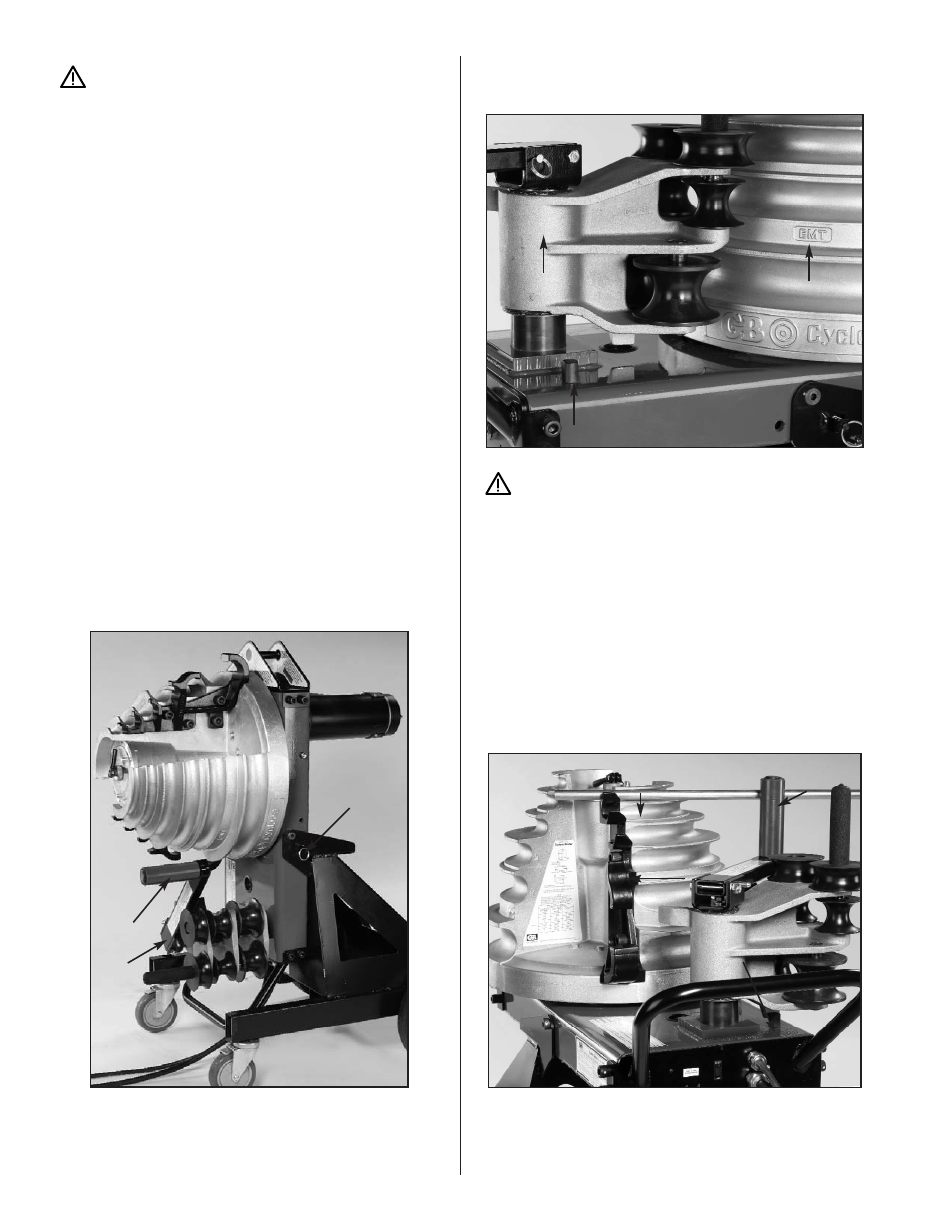
CAUTION: To avoid damaging the rollers and roller
housing, always place the roller housing against the
frame stop prior to rotating the shoe.
4.
Push the roller housing against the frame stop.
See Figure 2. Rotate the shoe to bring the required
grooves (EMT, IMC or Rigid) facing toward the operator.
To activate the shoe, hold the pendant toggle switch in
“Return” and press the jog button until the zero light goes
out. The shoe will rotate and stop in the load position. The
zero light will come on.
5.
The upper urethane roller and support arm (See Figure 4)
is used for bending
1
⁄
2
" through 1" conduit. One of the
top three shoe grooves will be used, depending on
conduit size.
Figure 4. Bending 1/2" - 1"
2
Support
Arm
Positioning
Pin
Upper
Roller
Roller Housing
Frame Stop
Material
Identifier
Frame Stop
Jaw
Bend Groove
Upper Roller