Lvds interface – Ampro Corporation XTX 820 User Manual
Page 46
Chapter 3
Hardware
40
Reference Manual
XTX 820
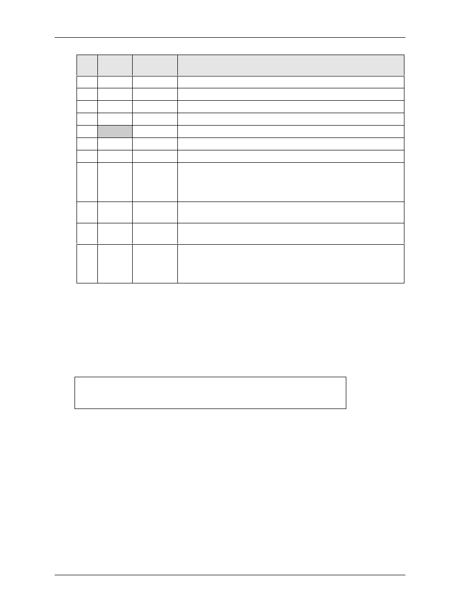
Table 3-20. Simplified CRT Interface Pin/Signal Descriptions (J3)
J3
Pin #
Signal
VGA
15-Pin #
Description
3
RED
1
Red – This is the Red analog output signal to the CRT.
6
GREEN
2
Green – This is the Green analog output signal to the CRT.
4
BLUE
3
Blue – This is the Blue analog output signal to the CRT.
NC
NC
4
Not Connected
GND
5, 6, 7, 8, 10
Ground
NC
NC
9
Not Connected
NC
11
Not Connected
10
DDDA
12
Display Data Channel Data – This signal line provides information to
the Memory & Graphics Hub about the monitor type, brand, model.
This is part of the Plug and Play standard developed by the VESA
trade association.
5
HSYNC
13
Horizontal Sync – This signal is used for the digital horizontal sync
output to the CRT.
7
VSYNC
14
Vertical Sync – This signal is used for the digital vertical sync output
to the CRT.
8
DDCK
15
Display Data Channel Clock – This signal line provides the data clock
signal to the Memory & Graphics Hub from the monitor. This is part
of the Plug and Play standard developed by the VESA trade
association.
Note: The shaded area denotes power or ground.
LVDS Interface
The LVDS interface is dedicated and independent of the other video interfaces and provides the
following features:.
• Supports ANSI/TIA/EIA-644-2001 specification compliance
• Supports 25 to 112 MHz single/dual channel LVDS interface with Spread Spectrum Clocking (SSC)
NOTE
Spread Spectrum Clocking is controlled in BIOS Setup under the
Advanced menu. Refer to Chapter 4, BIOS Setup for the Clock
Configuration where you can set the Spread Spectrum Clock.
• Supports maximum TFT pixel format of 1x18 bpp for one channel and 2x18 bpp for 2 channels
• Supports flat panel size up to UXGA (1600 x 1200)
• Supports Wide panel size up to WUXGA (1920 x 1200)
• Provides Automatic Panel Detection using EPI (Embedded Panel Interface based
on VESA EDID™ 1.3)
• Supports Intel® Display Power Savings Technology 2.0
Refer to Table 3-21 for the Simplified LVDS Interface Pin/Signal Descriptions.