Burkert Type 8645 User Manual
Page 12
12
EXPANDING A VALVE TERMINAL
Step 2:
Detach any FE rails from the back of the valve
→
terminal.
Detach the module to be replaced from the wall
→
or top hat rail.
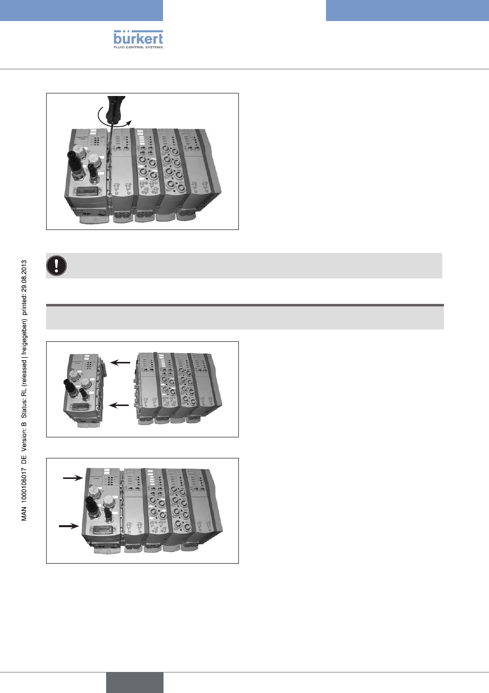
Then release and disengage the 3 locking pins by
→
turning them anti-clockwise through 90°.
In the released position the slots in the locking pins
are horizontal. The locking pins project over the
contact surface of the connecting bracket.
Releasing the locking pins
Fig. 16:
By applying gentle lateral pressure to the exposed side areas of the valve terminal in the vicinity of the cor-
responding locking pins, they can be supported as they are snapped out.
NOTE!
If the modules are removed without disengaging the locking pins, the modules may be damaged.
Step 3:
By snapping out the three locking pins, the head
module is released from the valve terminal and can
be removed without difficulty.
To do this, remove the head module parallel from
→
the side of the terminal.
Removing the head module
Fig. 17:
Step 4:
To attach the new head module, proceed in reverse
sequence.
First grease the seals and O-rings on the module.
→
Then press the module onto the side of the valve
→
block.
Ensure that O-rings, seals and electrical plug-and-
socket connections are not damaged.
Attaching the head module
Fig. 18:
english
Type 8645