Brooks Instrument 3600 Series User Manual
Page 23
2-3
Section 2 Installation
Installation and Operation Manual
X-VA-MT3600-eng
Part Number: 541B075AAG
February, 2011
Models MT3600, MT3601 & MT3602
2-7 Installation, MT3600 Series
The Model MT3600 Series is installed as follows:
a. Carefully remove the covers or plugs from the inlet and outlet of the
flowmeter.
b. The flowmeter must be installed with the inlet at the bottom and the
outlet perpendicular to the inlet. The indicator housing can be rotated
360°, for easy viewing, by loosening and then tightening the three set
screws at the base of the indicator housing.
c. When installing the flowmeter in the process line, follow accepted
plumbing practices.
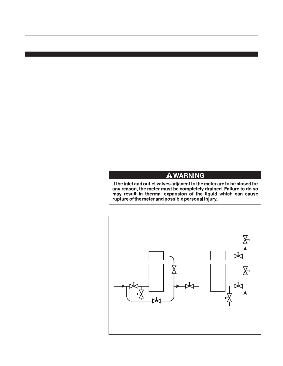
d. It is strongly recommended that the bypass piping arrangement
shown in Figure 2-1 be used when installing the flowmeter. This
arrangement will allow the flowmeter to be removed for repair or
service without interrupting the flow stream.
e. Install the flowmeter within five degrees of true vertical. Use a level to
verify the alignment of the flowmeter. Accurate alignment to vertical is
required to maintain flowmeter accuracy.
A - Inlet Valve
B - Outlet Valve
C - Bypass Valve
D - Control Valve
E - Drain Valve
HORIZONTAL
LINE
D
A
E
C
VERTICAL
LINE
B
B
A
E
FLOWMETER
C
D
FLOWMETER
FIgure 2-1 Typical Installations