0 maintenance and troubleshooting, Problem, Cause – Brooks Instrument CMC Series User Manual
Page 13: Solution, 1 returning the cmc series for repair, Brooks instrument, llc, 407 west vine st, Hatfield, pa 19440, 2 return instructions, 0 _maintenance & troubleshooting
p.7
4.0 MAINTENANCE AND TROUBLESHOOTING
There are no general maintenance requirements for the CMC Series other than
periodic Zero adjustment. If the unit fails to operate when received or if the unit
appears damaged, notify Brooks immediately. Retain packaging materials for
inspection. Do not use if damaged. If the CMC Series is not going to be used
immediately, then replace the protective flange cover and store in suitable condi-
tions. If no obvious damage has occurred, a few simple checks can be made to
verify proper installation to common problems with the installation. If none of
these problems/solutions are applicable, then please contact a Brooks Applica-
tions Engineer for further assistance.
4.1 Returning the CMC Series for Repair
Please contact Brooks before returning unit for repair in order to review informa-
tion relative to your application. When returning a product to Brooks, the material
should be carefully packaged (including the Contamination Disclosure Form)
and shipped prepaid to:
BROOKS INSTRUMENT, LLC.
407 WEST VINE ST.
HATFIELD, PA 19440
ATTN: REPAIR DEPARTMENT
4.2 Return Instructions
A disclosure of all chemicals exposed to the equipment to enable us to protect
our personnel and environment and to determine if special handling is required
to process your repair. Therefore, a Contamination Disclosure Form must be
completed (See Figure 6). Please place a copy of the completed Contamination
Disclosure Form on the exterior of the shipping container and include the original
alongside the product being returned.
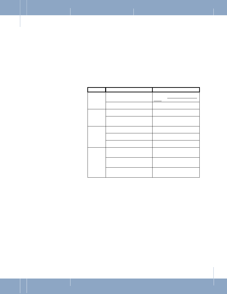
Problem
Cause
Solution
No signal
output
Incorrect or no supply voltage
Ensure power supply is used as
specified in “Electrical Installation” on
page 3
Readout display short circuit or
incorrect impedance
Ensure impedance of readout unit is
>10k ohm
Signal output
reads over-
range
Incorrect wiring
Ensure wiring conforms to diagrams in
Figure 3, Figure 4, or Figure 5.
Potential difference between chassis
ground of unit, power supply, and
readout/display
Ensure common chassis ground
between unit, power supply, and
display.
Signal output
reads under-
range
Incorrect Zero adjustment
Adjust zero per “Checking and Zero
Adjustment” on page 6.
Readout display incorrect impedance
Ensure impedance of readout unit is
10k ohm.
Incorrect wiring polarity to readout
display
Ensure wiring conforms to diagrams in
Figure 3, Figure 4, or Figure 5.
Unstable
signal
Chassis ground not connected
Ensure common chassis ground
between unit, power supply, and
display.
Unstable or unregulated supply
use a regulated power supply power
supply power supply as specified in
“Electrical Installation” on page 3.
Electrical noise on chassis ground
Ensure common chassis ground
between unit, power supply, and
display.
4.0
_MAINTENANCE & TROUBLESHOOTING