Flowline LD35 DeltaSpan User Manual
Page 14
14 of 16
MN301035
Rev B
INSTALLATION
Step Nine
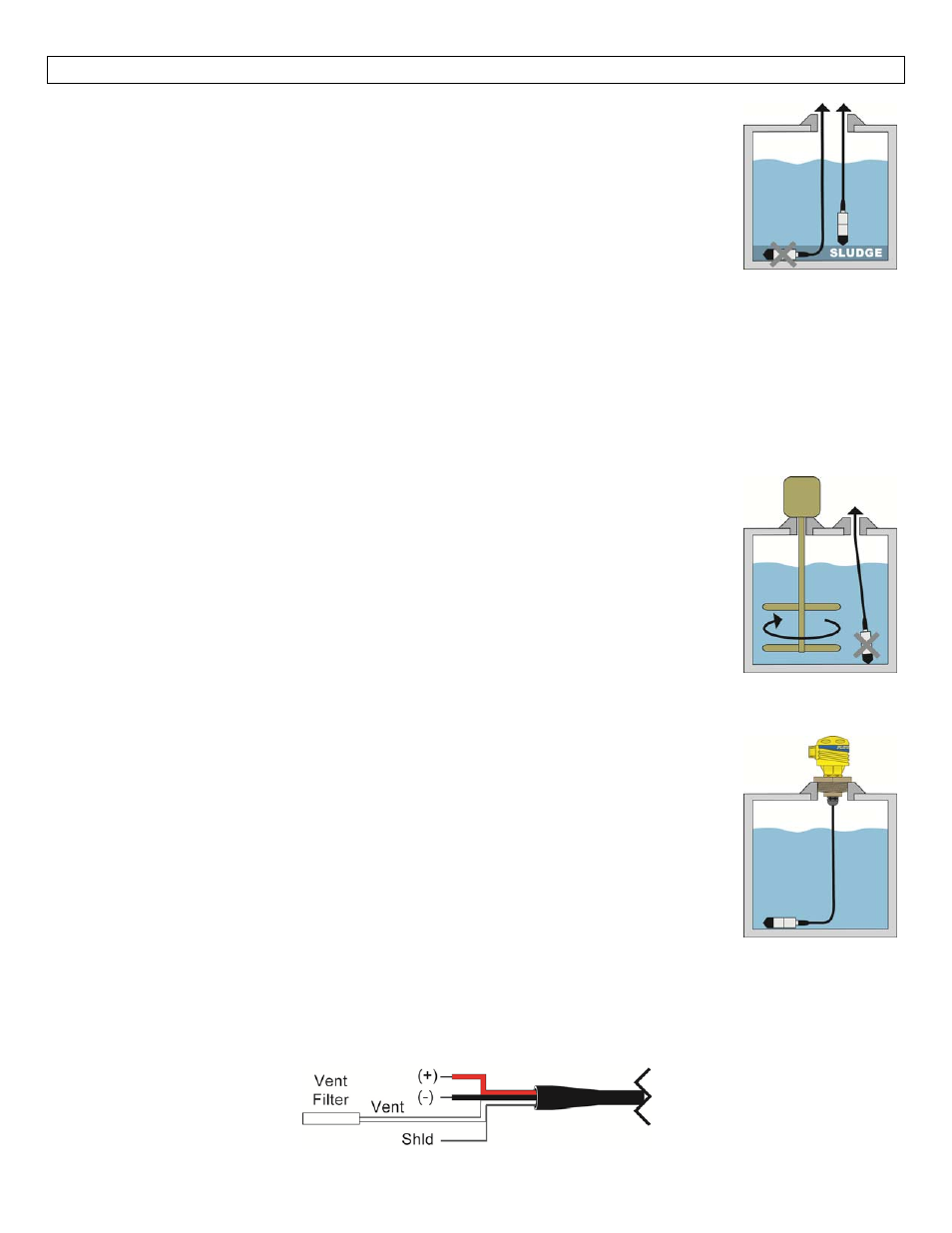
The LD34 / LD35 series are designed to operate while submerged in the actual
application liquid. Avoid installing the level transmitter along the bottom of the tank as
materials such as sludge will build up and coat/cover the transmitter. This also includes
any debris that will settle along the bottom of the tank. In these applications, it is best
to suspend the transmitter above the highest level of sludge/debris that will occur.
1. Location: Select a location where the temperature of the transmitter will be
between 0 and 176°F (‐18 to 80°C). Distance from the receiver is limited only by
total loop resistance.
2. Position: The transmitter is not position sensitive. However all standard models are originally
calibrated with the unit in a position with the pressure connection downward. Although they can be
used at other angles, for best accuracy it is recommended that units be installed in the position
calibrated at the factory.
3. Mounting: The transmitter can be mounted via several methods. It can be suspended from the
electrical cable, or it can be placed resting on the bottom of the tank in either horizontal or vertical
orientation.
Interference: The DeltaSpan™ is designed to operate under the surface of the liquid in
the tank. Avoid installations where other tank requirements will cause the transmitter
to move or swing. For example: a mixer blade could cause the level transmitter to whip
around within the tank. An alternative would be to move the transmitter to a more
stable section of the tank or to install the LD34/LD35 series inside a still well/drop tube.
The still well/drop pipe will minimize the effects created by the mixer.
Termination: The cable for the DeltaSpan™ is typically terminated at a junction box
located on top of the tank. Since the vent tube is contained within the cable, the
pressure within the junction box must always be the same as the reference (typically
atmospheric) pressure for the liquid. The inside of the junction box must be clean, dry and free of moisture.
Add the optional pressure fitting (LD90‐_001) to complete the package. The LD90‐_001
features a 2” NPT thread for mounting and a liquid tight connector to seal the cable
interface.
Note: Use caution when sealing the cable at the top of the tank. The ventilation tube
must be open and free to allow air to flow back to the pressure diaphragm. Avoid
blocking the ventilation tube by compressing the cable. Always keep the cable
termination clean, dry and free of moisture and prevent liquid from entering the vent
tube.
Note: A vent Filter is provided on the end of the vent tube. If the application requires
the vent tube to be cut to length, then remove the vent filter and place on the end of the new end of the vent
tube.
Note: For extra protection against high humidity environments, Flowline offers the LD90‐3000 desiccant filter
that can be attached to the vent tube.