Flowline LD35 DeltaSpan User Manual
Page 11
Rev B
MN301035
11 of 16
ELECTRICAL INSTALLATION
Step Seven
Wire Length ‐ The maximum length of wire connecting the transmitter and receiver is a function of wire size
and receiver resistance. Wiring should not contribute more than 10% of the receiver resistance to total loop
resistance. For extremely long runs (over 1000 feet), choose receivers with higher resistance to minimize the
size and cost of connecting leads. Where wiring length is less than 100 feet, wire as small as 22 AWG can be
used.
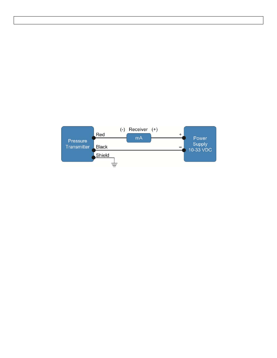
Wiring ‐ An external power supply delivering 13‐30 VDC for the LD31 and LD32 series with minimum current
capability of 40 mA DC (per transmitter) is required to power the control loop. See Fig. A for connection of the
power supply, transmitter and receiver. The range of appropriate receiver load resistance (RL) for the DC
power supply voltage available is expressed by the formula:
RLmax = (Vsup – 10V) / 20 mA DC
Shielded cable is recommended for control loop wiring. Use the Red wire as the (+) and the Black wire as the
(‐).
Fig. A
Black Wire is negative (‐) and Red Wire is positive (+).