Installation guide - for key in knob lock – Emtek Key In Knob with Round Rosette (Adjustable Latch) User Manual
Page 2
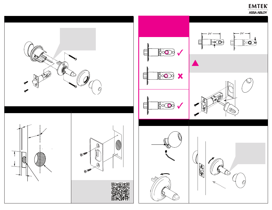
23/8” Backset
Correct Hub Position
23/8” Backset
Wrong
Hub Position
23/4” Backset
Correct Hub Position
IN4-KEYNKNOB
Rev. 02/26/2013
Installation Guide - For Key in Knob Lock
Lock Assembly
Door Prep
1. Adjust and Install Latch
Install Strike Plate
Fasten Strike Plate using Two #8 x 3/4”
Wood Screws (provided).
Step 1. Adjusting for appropriate backset.
Step 2. Fasten Adjustable Latch using two #8 x 3/4” Wood
Screws (provided).
!
To remove Pin:
Push Plastic Latch Pin
through latch with
screwdriver.
Scan this
QR code for
installation
video
Plastic Latch Pin
Plastic
Latch Pin
The Adjustable Latch is factory shipped with a
2-3/4” backset position. Remove pin and slide
spindle hub forward for a 2-3/8” backset, then
reinsert the pin in the hole at the back of the
latch as shown.
Outside Trim
Inside Trim
Flat spindle
MUST
be in horizontal
position for
installation
2. Remove Inside Rosette
Step 2. Unthread rosette
counterclockwise to remove from
housing before installing on door.
Step 1. Remove inside knob by loosing
set screw w/ hex wrench
(provided).
3. Installing Inside Trim
Step 1. Secure inside rosette to door by threading it clockwise on
to stem.
Step 2. Tighten set screw after placing knob on stem.
Plunger spindle
MUST
be in horizontal
position for
installation.
2-3/8”
or 2-3/4”
Backset
2-1/8”
Dia.
Bore
1/8
” Deep
2-1/4”
1 “
1” Diameter
Edge Bore
IMPORTANT!
CHECK LATCH HUB POSITION
BEFORE INSTALLING