Identification, Installation, Mechanical drawing – eLine Technology AN1 Series User Manual
Page 5: Installation information, Accessories fixed lens model
NOTE: Make sure you don’t have any missing parts before you make the installation.
Incorrect installation could void the warranty if instructions are not followed correctly.
Please call technical for assistance if you are unsure about any procedures.
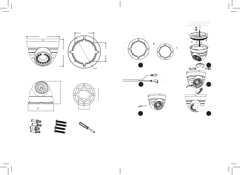
Identification
Mechanical Drawing
Installation
Installation information
(General overview)
Accessories
Fixed Lens Model
(B) Fitting Screws
PA4 x 35mm 4pc
(A) Wall Plugs
S8 x 30mm 4pc
(C) Adjustment Tool
Vari-Focal Model
70 mm
3"
70 mm
3"
Ø 120 mm
4 1/2"
120 mm
4 1/2"
100 mm
4"
94
80
49
49
1
Use the base as drill template. (Left is vari-focal model right fixed lens model)
2
Once base is firmly drilled into place, re-assemble parts.
3
Attach power and video. Make sure power + and - are correct
4
Position camera to suite make tight using the ring
5
Adjust the zoom & focus using the tool provided (Vari-Focal models)
6
Wipe clean the front glass to stop potential IR Led smear at night.
7
Check IR LEDs working by just covering the photocel of camera
with your thumb, the IR LEDs will give a faint red glow.
1
4
3
2
5
6
70
70
120
Focus adjustment
Zoom adjustment
Adjust wrench
Pan 360°
Three axis rotate
VIDEO
12VDC
Ceiling
CLOSE
OPEN
48
48
94
7
8