Identification, Installation, Mechanical drawing – eLine Technology AN1 Series User Manual
Page 3: Installation information, Accessories
3
4
NOTE: Make sure you don’t have any missing parts before you make the installation.
Incorrect installation could void the warranty if instructions are not followed correctly.
Please call technical for assistance if you are unsure about any procedures.
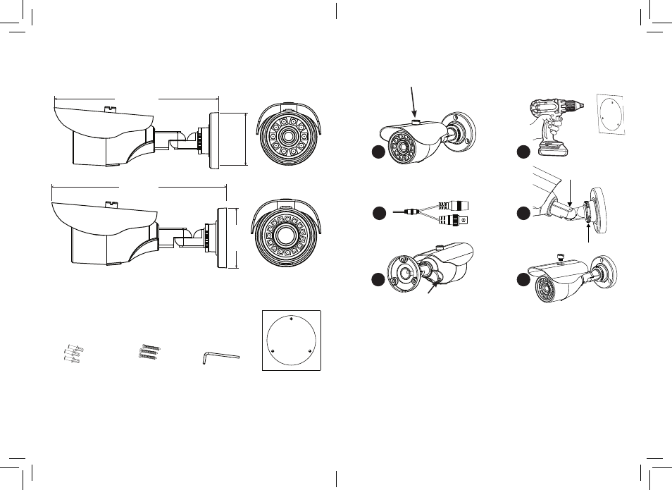
Identification
Mechanical Drawing
Installation
Installation information
(General overview)
4
1
Remove visor from camera to aid simpler installation. (Optional requirement)
2
Use drill template (D) as to guide to drill and attach camera to surface as required.
Holes on bracket are 120 degree apart, so three holes are required.
3
With camera attached you can now connect power, check device working.
4
Using the (C) L-Hex tool you position left-right up/down and lock into place.
The rear position rotation allows turning of angle turn anti-clockwise to loosen.
5
Adjust zoom & focus using small flat blade. (Vari-focal model only)
6
Replace the sun visor if removed from step 1.
Check IR LEDs are working by covering the photocell of camera, the IR LEDs will
give a faint red glow.
(Don’t look at IR LEDs for long periods of time, as you could damage your eyes)
Accessories
(C) L-Hex tool
54x18mm
(D ) Drill template
(B) Fitting Screws
PA4 x 24mm 3pcs
(A) Wall Plugs
S7 x 26mm 3pcs
1
4
3
2
5
6
194 mm
7 5/8 in
62 mm
2 3/8 in
226 mm
8 7/8 in
77 mm
3 in
Locking Screw
Rotation lock