Identification, Installation, Mechanical drawing – eLine Technology AN2 Series User Manual
Page 4: Installation information, Accessories vari-focal lens model
5
6
NOTE: Make sure you don’t have any missing parts before you make the installation.
Incorrect installation could void the warranty if instructions are not followed correctly.
Please call technical for assistance if you are unsure about any procedures.
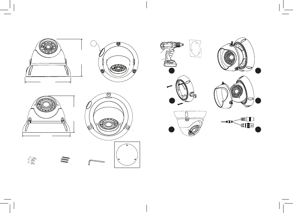
Identification
Mechanical Drawing
Installation
Installation information
(General overview)
6
Accessories
Vari-Focal Lens Model
118 mm
4 5/8 in
99 mm
3 7/8 in
1/2”
152 mm
6 in
117.5 mm
4 5/8 in
(C) L-Hex tool
58x20mm
(D ) Drill template
(B) Fitting Screws
PA4 x 24mm 3pcs
(A) Wall Plugs
S7 x 26mm 3pcs
1
Use supplied template to drill holes for (A) plugs.
2
Remove locking cover using supplied (C) L-key. Optional requirement
3
Attach base part to surface with (B) screws. Use conduit if required.
4
Re-attach Cover and position camera then lock cover screws with L-Key.
5
Adjust the zoom & focus using flat blade tool. (Vari-Focal models only)
6
Connect power, feeding through conduit may require this stage to be
completed before adjustment is made. Check IR LEDs are working by
covering the photocell of camera, the IR LEDs will give a faint red glow.
(Don’t look at IR LEDs for long periods of time, as you could damage your eyes)
1
4
3
2
5
6