Hardware setup – Asus P4T-F User Manual
Page 35
ASUS P4T-F User’s Manual
35
3. HARDWARE SETUP
Connectors
3. H/W SETUP
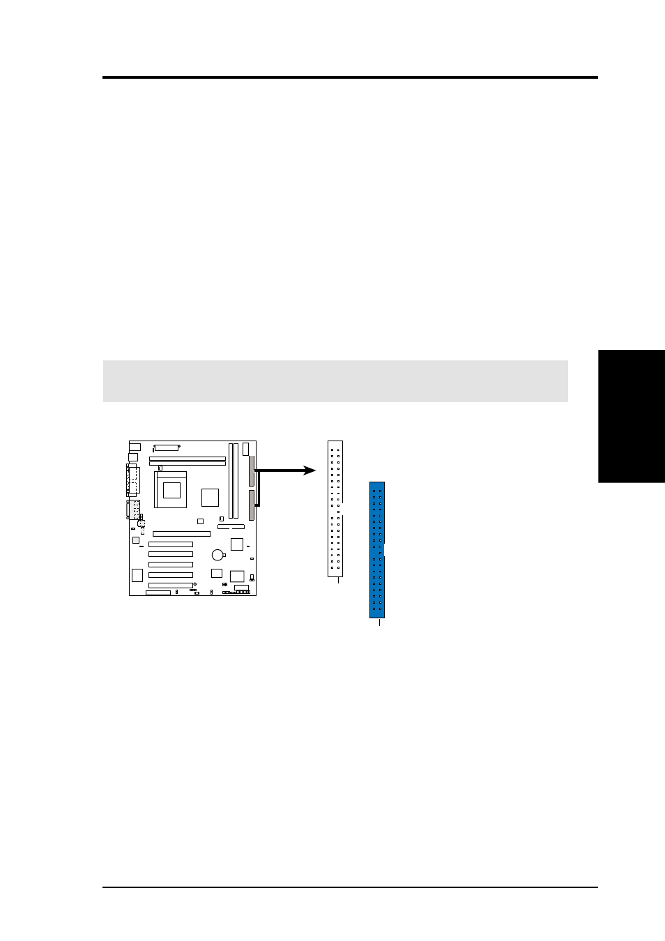
9) Primary (Blue) / Secondary IDE Connectors (Two 40-1pin IDE)
These connectors support the provided IDE hard disk ribbon cable. Connect the
cable’s blue connector to the motherboard’s primary (recommended) or second-
ary IDE connector. Then connect the gray connector to your UltraDMA/100
slave device (hard disk drive) and the black connector to your UltraDMA/100
master device. It is recommended that non-UltraDMA/100 devices be connected
to the secondary IDE connector. If you install two hard disks, you must config-
ure the second drive to Slave mode. Please refer to your hard disk documenta-
tion for the jumper settings. BIOS now supports specific device bootup (see 4.6
Boot Menu).
(Pin 20 is removed to prevent wrong orientations).
TIP: You may configure two hard disks to be both Masters with two ribbon
cables – one for the primary IDE connector and another for the secondary IDE
connector. You may install one operating system on an IDE drive and another
on a SCSI drive and select the boot disk through 4.6 Boot Menu.
IMPORTANT:
UltraDMA/100 IDE devices must use a 40-pin 80-conductor IDE
cable for 100MByte/sec transfer rates.
P4T-F
P4T-F IDE Connectors
NOTE: Orient the red markings
(usually zigzag) on the IDE
ribbon cable to PIN 1.
Secondary IDE Connector
PIN 1
Primary IDE Connector
PIN 1