Datamax-O'Neil I-Class GPIO Multi-Expansion Option User Manual
Page 6
4
GPIO Port – A General Purpose Input / Output Port for control of printing functions via an external
device (e.g., a label applicator), as detailed below:
Pin
Number
Signal
Name
Signal
State
Signal
Direction *
Description
1 Vcc +5
VDC
Output
+5 VDC power supply.
2 Ribbon
Fault
Low
Output
Goes low when a ribbon out
condition is detected.
3 Paper
Fault
Low
Output
Goes low when an out of stock
condition is detected.
4 Printer
Fault
Low
Output
Goes low when any printer fault
is detected.
5 Ribbon
Low
Programmable
Output
Goes high (or low) when a low
ribbon supply is detected.
6
End of Print
Programmable
Output
Goes high (or low) when printing
is complete, typically monitored
to initiate the next Start of Print
sequence.
7 Backup
Label
Programmable Input
When received, will position a
presented label for printing --
provided that the programmed
present distance is greater than
zero.
8
Start of Print
Signal (SOP)
Programmable
Input
When received, begins printing.
(If the printer awaits the SOP
signal, WAITING FOR SIGNAL
will be displayed).
9 Signal
Ground Ground
N/A
Ground return.
*
Signal direction is given relative to the printer.
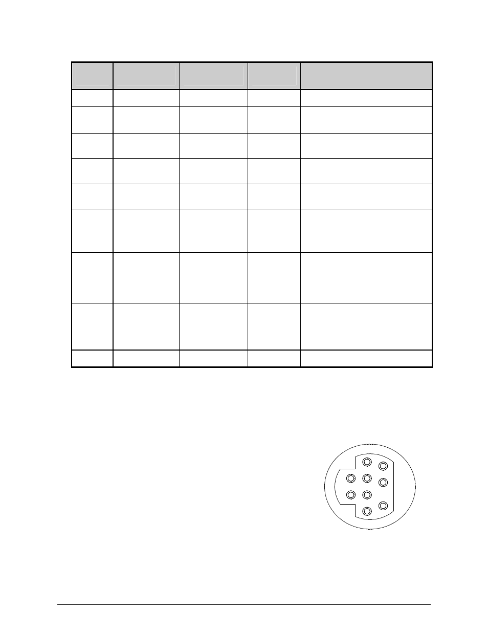
The GPIO Connector pin out configuration, illustrated, right, as
viewed from the rear of the printer. (Use a Mini-DIN male
connector [e.g., Kycon KMDA-9P] when making your interface).
1
2
3
4
5
6
7
8
9