Datamax-O'Neil H-Class GPIO Option User Manual
Page 6
4
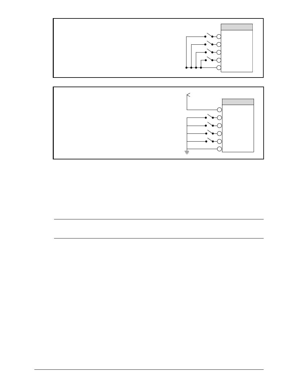
For direct inputs –
Use the printer’s +5VDC and Ground to supply
the devices interfacing to the GPI/O A inputs
(as shown in the sample circuit, right).
GPI/O A - J1
3
4
5
6
1
Start of Print
Slew Label
Toggle/Pause
Reprint
Ground
For isolated inputs –
To provide galvanic isolation for the GPI/O A
inputs, remove Jumper JMP 9 then supply an
external +5VDC source voltage to Pin 2, and
remove Jumper JMP 8 then supply an external
Ground to Pin 1 (as shown this sample circuit,
right).
3
4
5
6
2
Start of Print
Slew Label
Toggle/Pause
Reprint
Vcc
+5 VDC External Source
GPI/O A - J1
1
Ground
Seven dedicated outputs are available for control, warning, and error functions.
These open-collector outputs have slew-limited signal-edge rise and fall times to
prevent cross talk in the cabling. Optional 10K ohm pull-up resistors, tied to a
common point for use at either +5 or +24 VDC, are available via Jumper JMP 1.
Note: If external pull-ups are used (that is, without Jumper JMP1 installed),
ensure that the applied external voltage does not exceed +30VDC.
The table below details the GPI/O A pin assignments, settings and functions.