Datamax-O'Neil H-Class GPIO Option User Manual
Page 12
10
D) Place the Cover Plate (Item 2) onto
the Card Cage, as shown, then
install and tighten the two Screws
(Item 3) to secure the plate.
Cover Plate
Screws
Card Cage
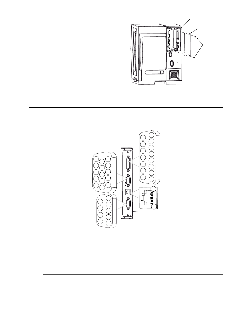
Step 3: Interfacing
Interface the card according to your application requirements (see the drawing below for
connector pin-outs, refer to Step 1 for signal details) as follows:
J2
J1
9
5
4
3
2
1
8
7
6
J4
1
6
11
5
4
3
2
9
8
7
10
15
14
13
12
15
14
13
12
11
10
9
8
7
6
5
4
3
2
1
8
1
J3
A) For GPIO functions connect a GPI/O interface cable to the GPI/O A (J1) and / or GPI/O
B (J2) ports.
B) For RS232 communications connect a serial interface cable to COM C (J4) and / or COM
D (J3); for dedicated devices, connect the cabling from that device to COM C (J4).
Note: If using both the RFID and Linear Scanner, see Configuring Hardware
Settings, above.
C) Connect the AC power cord to the printer and then turn the power switch ON.
- MF8I 270 User Guide (20 pages)
- MF8I Installation Guide (18 pages)
- MF8I Truck Mount Cable (2 pages)
- MF8I Locking Mounting Bracket (2 pages)
- MF8I Economy Mounting Bracket (2 pages)
- MF8I AN-15 (Line Printer and Easy Print Modes) (7 pages)
- MF8I AN-16 (Single Byte Character Set Font File Format) (8 pages)
- MF8I Quick Reference Programming Guide (72 pages)
- MF8I Configuration Program Installation (1 page)
- MF8I Bluetooth Management Component for Wavelink Avalanche (10 pages)
- A-Class Mark II Operator’s Manual (160 pages)
- A-Class Mark II Installation (2 pages)
- A-Class Mark II DMXrfNetIII (16 pages)
- A-Class Mark II DMXrfNetII (16 pages)
- A-Class Mark II RFID Quick Start Guide (6 pages)
- A-Class Mark II Programmer’s Manual (334 pages)
- ANDES 3 User Guide (32 pages)
- ANDES 3 Quick Start Guide (2 pages)
- ANDES Series Programmer’s Manual (67 pages)
- APEX 2 User Guide (28 pages)
- APEX 2 Quick Start Guide (2 pages)
- APEX 3 User Guide (27 pages)
- APEX 3 Quick Start Guide (2 pages)
- APEX 4 User Guide (30 pages)
- APEX 4 Quick Start Guide (2 pages)
- E-Class Mark III Operator’s Manual (90 pages)
- E-Class Mark III 4xxxxxxx Operator’s Manual (58 pages)
- E-Class Mark III 3xxxxxxx Operator’s Manual (58 pages)
- E-Class Mark III Paper Menu (7 pages)
- E-Class Mark III DPL Programmer’s Manual (296 pages)
- E-Class Mark III Printhead Bracket and Screw Upgrade (11 pages)
- H-Class Operator’s Manual (180 pages)
- Static brush (2 pages)
- H-Class Media Retainer (1 page)
- H-Class Thermal Transfer Option (12 pages)
- H-Class RFID Option (8 pages)
- H-Class Powered Internal Rewind Option (10 pages)
- H-Class Internal Rewind Option (6 pages)
- H-Class Present Sensor Option (8 pages)
- H-Class Peel & Present Option (8 pages)
- H-Class Linear Scanner Option (26 pages)
- H-Class HD Peel & Present Option (10 pages)
- H-Class HD Cutter Option (12 pages)
- H-Class Cutter Option (10 pages)