BEI Sensors High Resolution Inclinometers User Manual
Page 3
Version 130305
CANopen Industrial Datasheet
Page 3
INCLI NO MET E R
CA NOPE N
Installation
Electrical Connection
The inclinometer is connected via 8 pin round
connector or a Cable
Instructions to mechanically install and
electrically connect the inclinometer
Do not connect the inclinometer
under power!
Do not stand on the inclinometer!
Avoid mechanical load!
Bus Termination
If the inclinometer is connected at the end or
beginning of the bus the termination resistor
must be switched on. The termination resistor is
switched on when the dip-
switch 8 is in the ‘ON’
position. To switch the resistor on, the cap of the
inclinometer have to unscrew.
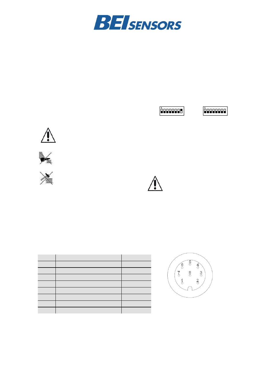
Tabelle 1 Connector Assignment
There is a resistor provided in the inclinometer,
which must be used as a line termination on the
last device.
ON
OFF
Bus address
The setting of the node number is achieved via
SDO-Object
(see
4.2).
Possible
(valid)
addresses lie between 0 and 96 whereby every
address can only be used once.
The CANopen inclinometer adds
internal 1 to the adjusted device
address.
Pin
Description
P8F-Cable
1
+UB Supply voltage
White
2
RxD
Brown
3
TxD
Green
4
Ground (Supply)
Yellow
5
CAN Low
grey
6
CAN Ground
Pink
7
CAN High
Blue
8
Red
Front view of housing
Connector inclinometer