BEI Sensors Industrial Duty Inclinometers User Manual
Page 7
Page 7
Analog Industrial Data Sheet
Version: 20130503
INDUST RIAL I NCLI NOME T ER
ANA LOG & RS 232 I NT ER F ACE
Pin Assignment
The inclinometer is connected via an 8 pin M12 A-coded round connector.
(Standard M12, Male side at sensor, Female at connector counterpart or connection cable).
For more detailed information about setup, measurement axes and
programming, refer INC-RS232_Analog Manual.
Please read the instruction leaflet carefully prior to installation.
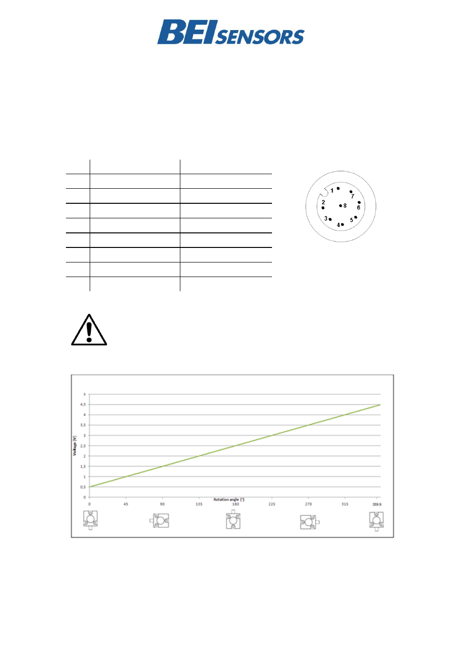
Voltage Output
1
Should not be connected
Pin
Description of INC-080
Description of INC-360
1
V
S
Supply Voltage
V
S
Supply Voltage
2
RxD (RS232 Receive)
RxD (RS232 Receive)
3
TxD (RS232 Transmit)
TxD (RS232 Transmit)
4
Ground
Ground
5
X-axis Analog Output
Z -Axis Analog Output
6
Preset/Set1 (Teach-In)
Preset/Set1 (Teach-In)
7
Y-axis Output Analog
Unused, Do Not Connect
8
DIR/Set 2 (Teach-In)
DIR/Set 2 (Teach-In)
INC-360
– Voltage Output