Input/output pin control, Outputs, Input/output pin control outputs – ALLIED Vision Technologies Bigeye G-1100 Cool User Manual
Page 44
Camera interfaces
Bigeye G Technical Manual V2.1.0
44
Input/output pin control
All input and output signals running over the camera I/O connector are con-
trolled by the I/O strobe commands. See AVT GigE GenICam Feature Descrip-
tion and AVT GigE Vision Cameras.
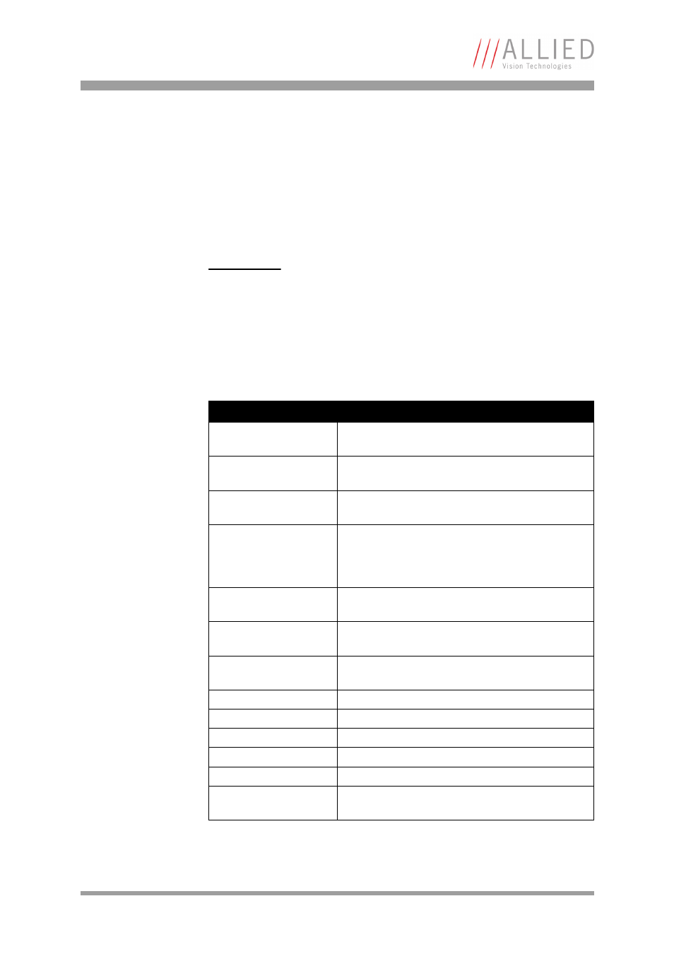
Outputs
Output features are configured by software. Any signal can be placed on any
output.
The main features of output signals are described below:
Note
For a general description of the outputs and warnings see the
AVT GigE Installation Manual.
Signal
Description
GPO
Configured to be a general purpose output, control
of which is assigned to SyncOutGpoLevels.
AcquisitionTriggerReady Active once the camera has been recognized by the
host PC and is ready to start acquisition.
FrameTriggerReady
Active when the camera is in a state that will accept
the next frame trigger.
FrameTrigger
Active when an image has been initiated to start.
This is a logic trigger internal to the camera that is
initiated by an external trigger or software trigger
event.
Exposing
Exposing – active for the duration of sensor expo-
sure.
FrameReadout
Active at during frame readout, i.e. the transfer-
ring of image data from the CCD to camera memory.
Imaging
Imaging is high when the camera image sensor is
either exposing and/or reading out data.
Acquiring
Active during an acquisition stream.
SyncIn1
Active when there is an external trigger at SyncIn1.
SyncIn2
Active when there is an external trigger at SyncIn2.
SyncIn3
Active when there is an external trigger at SyncIn3.
SyncIn4
Active when there is an external trigger at SyncIn4.
Strobe1
The output signal is controlled according to Strobe1
settings.
Table 12: Output signals