Control signals, Inputs – ALLIED Vision Technologies Bigeye G-1100 Cool User Manual
Page 43
Camera interfaces
Bigeye G Technical Manual V2.1.0
43
Control signals
The inputs and outputs of the camera can be configured by software. The differ-
ent modes are described below.
Inputs
15 Camera Out 2
Out
Open emitter,
max. 20 mA
Camera Output 2
(GP Out 2)
16 Camera In 2
In
Max. 24.0 V
Camera Input 2
(GP In 2)
17 Camera In 4
In
3.3 V TTL
Camera Input 4 (GP In
4)
18 ---
---
---
Reserved
19 RxD 2
In
RS232
Terminal Receive Data
2
20 TxD 2
Out
RS232
Terminal Transmit Data
2
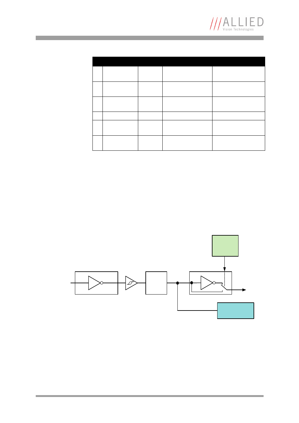
Figure 9: Input block diagram
Pin Signal
Direction Level
Description
Table 11: Camera I/O connector pin assignment (HD20 Mini D Ribbon)
Polarity
selectable
via software
Input state
Input signal
Opto-
Coupler
LP filter
This manual is related to the following products: