CHIEF QMP1L User Manual
Page 5
Installation Instructions
QMP1L
5
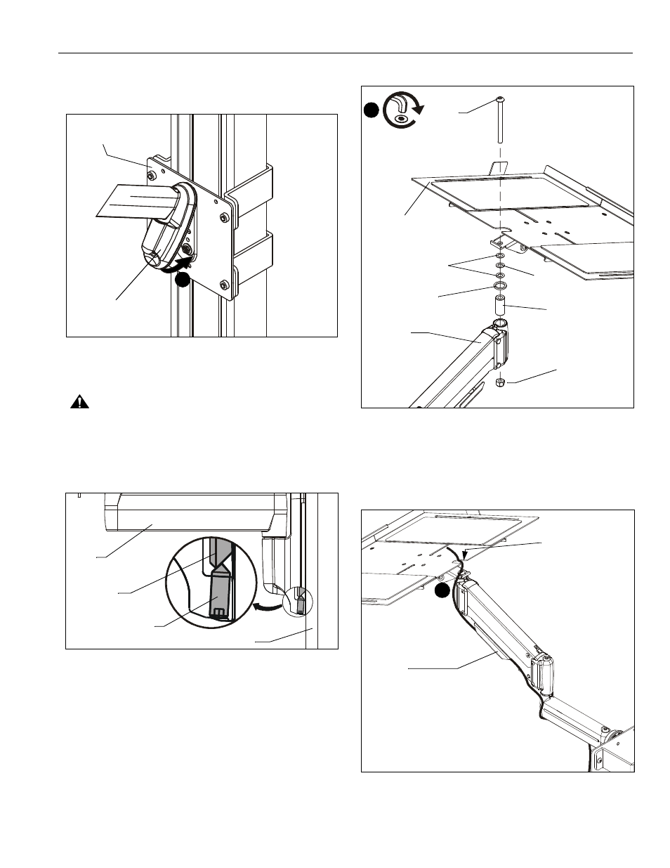
6.
Swing height-adjust assembly (C) down flush against
attachment plate assembly. (See Figure 4)
Figure 4
7.
Tighten set screw using 5/32" hex key (R). (See Figure 5)
CAUTION:
IMPROPER INSTALLATION CAN LEAD TO
ACCESSORY FALLING CAUSING SERIOUS PERSONAL
INJURY OR DAMAGE TO EQUIPMENT! Make sure set
screw engages back side of bracket on attachment plate.
(See Figure 5)
Figure 5
Assembling Laptop Tray Assembly to Cart/Stand
1.
Attach laptop tray assembly (D) to height adjust assembly
(C) using one 5/16-18 x 3-1/2" button head cap screw (M),
two .018" spacers (W), one UHMW washer (U), one pivot
pin (H), one UHMW washer (T), and one 5/16" nylon lock
nut (V). (See Figure 6)
Figure 6
Cable Management
1.
Thread laptop cable through slot along the back edge of
laptop tray and down along the side of the height-adjust arm
to the cable management bracket. (See Figure 7)
Figure 7
(C)
6
Attachment
plate assembly
Cart/stand column
(C)
(B)
Set screw
1
(M) x 1
(D)
(H)
(C)
(V)
(U)
(W) x 2
(T)
1
Slot
Cable management
bracket