Assembly and installation – CHIEF QMP1L User Manual
Page 4
QMP1L
Installation Instructions
4
ASSEMBLY AND INSTALLATION
Assembling Height-Adjust Arm to Cart/Stand
WARNING:
IMPROPER INSTALLATION CAN LEAD TO
EQUIPMENT FALLING CAUSING SERIOUS PERSONAL
INJURY OR DAMAGE TO EQUIPMENT! DO NOT substitute
hardware! Use only hardware provided by manufacturer.
WARNING:
EXCEEDING MAXIMUM WEIGHT CAPACITY
MAY LEAD TO SERIOUS PERSONAL INJURY OR
DAMAGE TO EQUIPMENT! It is the user’s responsibility to
ensure the total amount of weight placed on the laptop stand
does not exceed 15 lbs (6.8 kg).
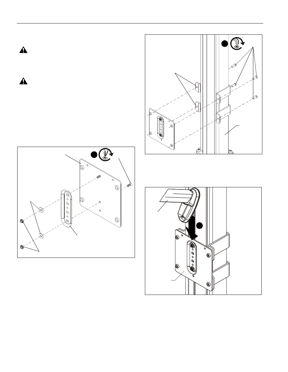
1.
Align bracket (B) with attachment plate (A), lining up rivet on
attachment plate with top mounting hole on bracket.
2.
Fasten bracket (B) to attachment plate (A) using one
10-24 x 1/2" Phillips undercut metal screw (N), two #10 flat
washers (K) and two 10-24 nylon locknuts (J). (See Figure 1)
Figure 1
3.
Choose appropriate array clamps to complete bracket
assembly to cart/stand.
•
Array clamp, outer (F) is used to attach height-
adjust assembly (C) to OUTER column of cart/
stand (below adjustment knob).
•
Array clamp, inner (E) is used to attach height-
adjust assembly (C) to INNER column of cart/
stand (above adjustment knob).
4.
Attach two array clamps (E or F) around cart/stand column to
attachment plate assembly using four 1/4-20 x 3/4" button
head cap screws (L). (See Figure 2)
Figure 2
5.
Insert top of height-adjust assembly (C) over lip on top of
attachment plate assembly. (See Figure 3)
Figure 3
1
(N) x 1
(K) x 2
(J) x 2
(B)
(A)
1
(L) x 4
(E or F) x 2
[Array clamp, inner shown]
QMP1FB or
QMP1MB
5
Attachment
plate assembly
(C)