Installation – CHIEF TA250 User Manual
Page 6
TA100/200/250
Installation Instructions
6
Installation
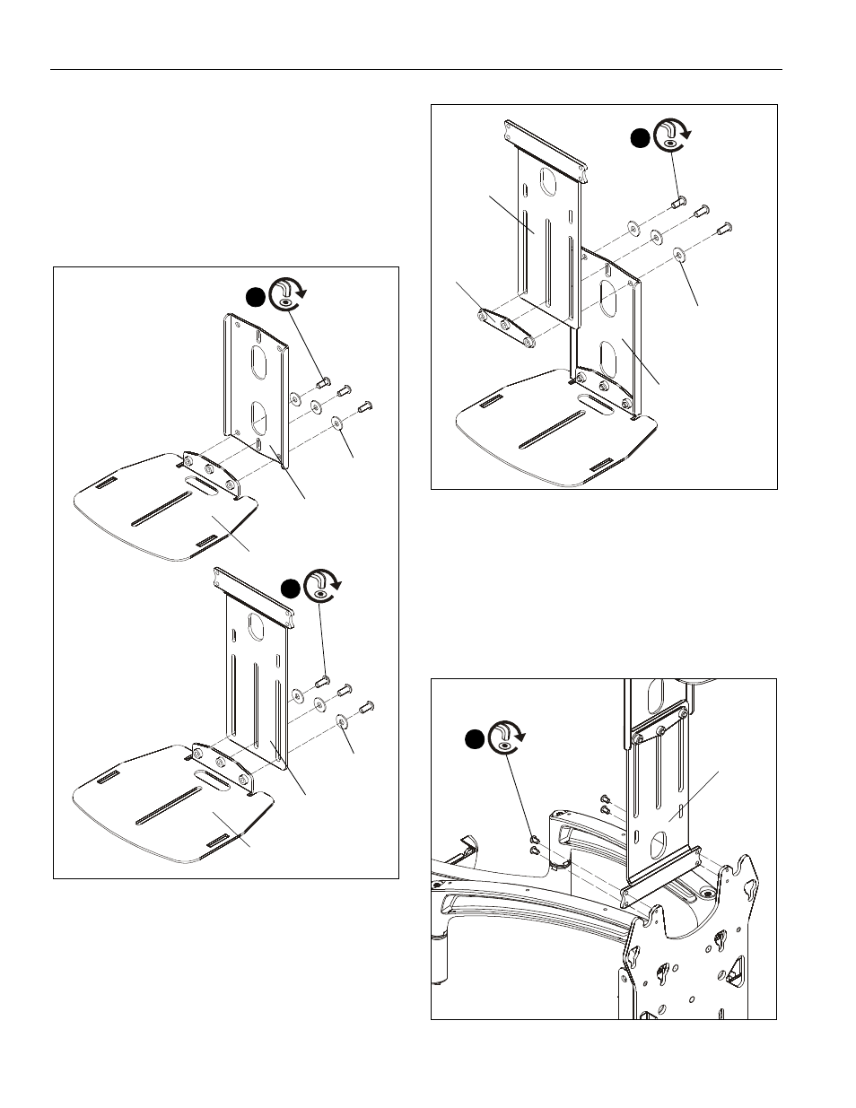
Shelf Assembly
1.
Use three 1/4-20 x 5/8" button head cap screws (F) and
three 1/4" washers (G) to connect shelf (C) to either
extension bracket (B) or attachment bracket (A). (See
Figure 1)
NOTE:
Use extension bracket (B) for larger displays or if
component needs to be mounted further from the
display.
Figure 1
2.
If using extension bracket, use three 1/4-20 x 5/8" button
head cap screws (F) and three 1/4" washers (G) to attach
extension bracket (B) to attachment bracket (A). (See
Figure 2)
Figure 2
Installation to Faceplate
TS525 or iCF50 Installation
NOTE:
Display does NOT have to be removed for shelf
installation.
1.
Use four #10-24 x 3/8" button head cap screws (E) to
connect attachment bracket (A) to swing arm faceplate.
(See Figure 3) and (See Figure 4)
Figure 3
1
(F) x 3
(G) x 3
(B)
(C)
(TA200 shown)
1
(F) x 3
(G) x 3
(A)
(C)
With extension bracket
Without extension bracket
2
(F) x 3
(G) x 3
(A)
(D)
(B)
(TA200 shown)
(display not shown for clarity)
(upper installation)
(A)
(E) x 4
1