CHIEF KTA320_325 User Manual
Page 5
Installation Instructions
Models: KTA-220/225 and KTA-320/325
5
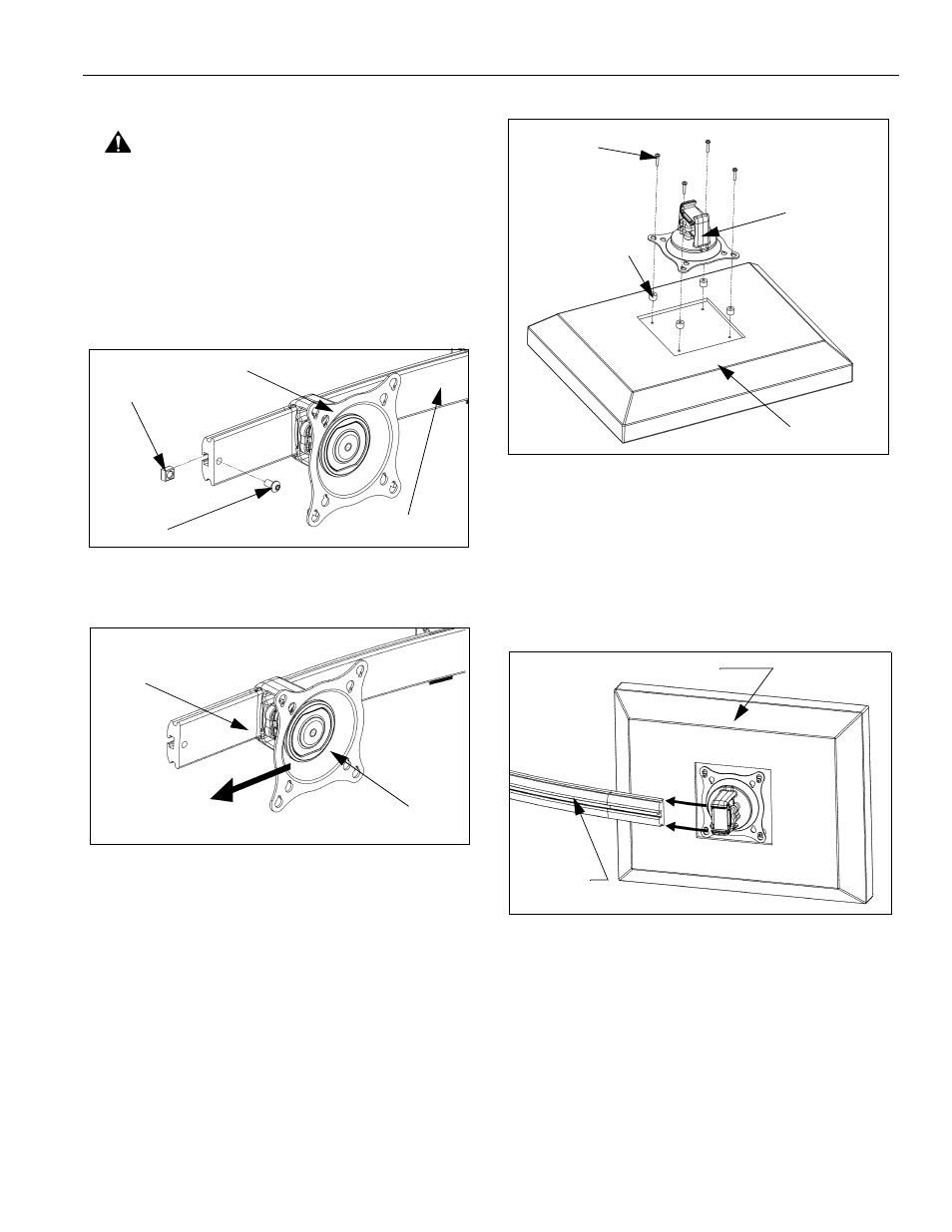
Attach Centris Head to Recessed Mount Display
CAUTION: If display uses a screw size other than
those included in the kit, DO NOT use the screws
provided. Using the wrong screws could result in
damage to your monitor.
1.
Uninstall end lock using the 5/32" hex key (80).
(See Figure 6)
2.
Remove Centris head from mounting rail.
(See Figure 7)
Figure 6: Remove End Lock(s)
Figure 7: Slide Centris Bracket off Array Rail
3.
Place display face down on a clean dry surface.
4.
Place four 3/8" or 3/4" nylon spacers (60 or 70) over
four mounting holes in display back.
NOTE: Refer to Table 1 to select the applicable screw
and spacer combination.
5.
Align Centris head mounting holes with four nylon
spacers.
6.
Secure Centris head to display using four
M4 x 20mm Phillips pan head screws (40), or four M4
x 30mm Phillips pan head screws (50).(See Figure 8)
Figure 8: Mount Centris Bracket to Display
7.
Slide display with Centris bracket onto mounting rail.
(See Figure 9)
NOTE: Repeat previous steps for each additional display.
8.
Install end locks into mounting rail using the 5/32" hex
key (80). (See Figure 10)
Figure 9: Mount Display with Centris Bracket to
Array Rail
Square Nut
End Lock
Centris Head
Array Rail
Centris Head
Array Rail
Display
Centris Head
Spacer (60 or 70)
Phillips Pan Head Screw
(40 or 50)
Display with Centris Bracket
Array Rail