CHIEF KSA1011 User Manual
Page 7
Installation Instructions
Model: KSA-1011
7
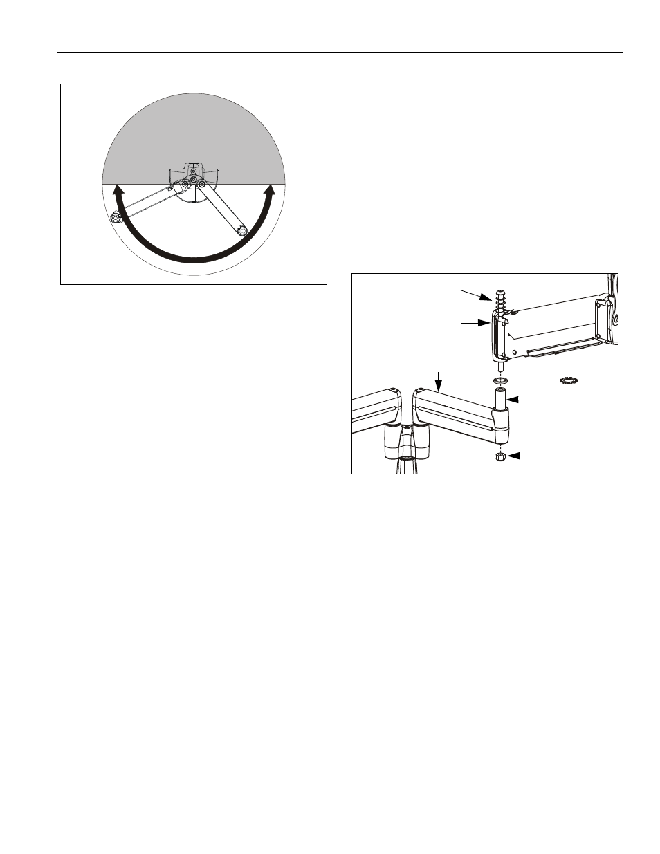
Figure 10: Allowable Arm Area
6.
Repeat Steps 1. through 5. for second mount arm
assembly (10).
7.
Install displays to mount. See instructions included
with mount and/or interface.
8.
Install cables to display.
9.
Assembly is complete. If desired, proceed to
"MODIFICATION OF MOUNT ARMS."
MODIFICATION OF MOUNT ARMS
If desired, each mount arm assembly may be modified to
prevent movement of one arm relative to the other arm
(without loosening screw).
NOTE: Spacer will allow limited movement of one arm
relative to the other arm, dependent upon tension
of screw. Washer (40) will lock arms together.
1.
If previously attached, disconnect cables from
display, then remove display. See instructions
included with mount and/or interface.
2.
Using 3/16" hex key, loosen screw until nut can be
removed (See Figure 11). Retain nut. Screw and
washers may remain in outer mount arm assembly.
Figure 11: Multi-Dual Arm Modification
3.
Lift outer mount arm assembly from pin (with screw
and washers) and place on protective surface.
4.
Remove spacer from pin (See Figure 11).
5.
Install washer (40) on pin (See Figure 11).
6.
Re-install outer mount arm assembly (with screw and
washers) on pin (See Figure 11).
7.
Insert and hold nut in lower bore of inner mount arm
assembly (See Figure 11).
8.
Tighten screw as required using 3/16" hex key (See
Figure 11).
9.
Install display(s) to mount. See instructions included
with mount and/or interface.
10. Install cables to display.
11. Modification is complete.
DO NOT POSITION EITHER
ARM IN GRAY SHADED AREA
ALLOWABLE
ARM AREA
Spacer or
40
Nut
Outer mount
Pin
Screw & Washers
arm assembly
Inner mount
arm assembly