Adjustments – CHIEF K1D Series User Manual
Page 12
K1D Series
Installation Instructions
12
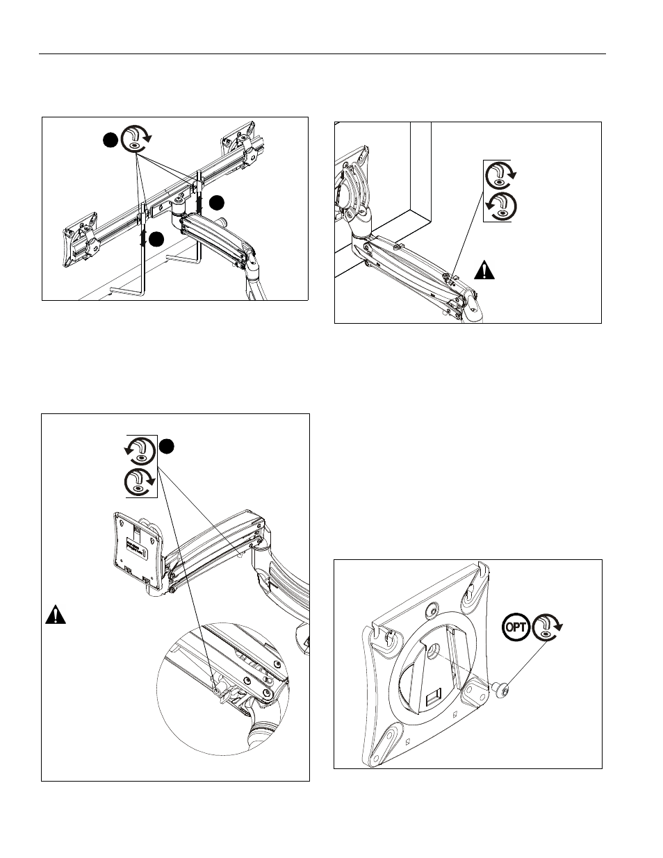
3.
Position handle (J2) at desired height and secure by
tightening button head cap screws attaching handle
brackets to array. (See Figure 15)
Figure 15
Adjustments
Lift Arm Tension Adjustment
1.
Use 3/16” hex key (K) to adjust lift arm tension adjustment
screw. (See Figure 16)
Figure 16
NOTE:
Tension may also be adjusted with upper tension
adjustment screw inside cable management cover and
1/8” hex key (L). (See Figure 17)
Figure 17
Pitch Adjustment (non-array models)
1.
Adjust pitch to desired tilt position. (See Figure 18)
2.
Adjust pitch tension screw to change the adjustment
tension. (See Figure 18)
Pivot Adjustment (non-array models)
3.
Adjust pivot position as desired. (See Figure 18)
4.
Use 3/16” hex key (K) to adjust pivot point tension screws to
change pivot adjustment tension. (See Figure 18)
Portrait Adjustment
NOTE:
(Optional) Rotational adjustment may be locked by
installing rotational locking screw (H) into back of
faceplate. (See Figure 18)
Figure 18
3
3
3
x 4
K1D120
1
Reduce tension
Increase tension
(lighter display)
(heavier display)
Do NOT over-tension
adjustment tension
screw.
underside view
Reduce tension
Increase tension
(lighter display)
(heavier display)
Do NOT over-tension
adjustment tension
screw.
(H)