Display installation - standard faceplate – CHIEF K1D Series User Manual
Page 10
K1D Series
Installation Instructions
10
Display Installation - Standard Faceplate
NOTE:
If installing mount that includes custom faceplate
(K1D120XXDL or K1D220XXDL), proceed to Display
Installation - Custom Faceplate Section.
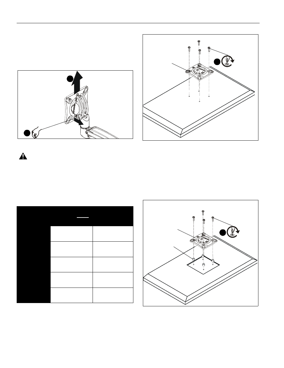
1.
Remove quick release faceplate from mount by pulling
quick release lever and sliding faceplate off mount. (See
Figure 8)
Figure 8
WARNING:
Exceeding the weight capacity can result in
serious personal injury or damage to equipment! It is the
installer’s responsibility to make sure the combined weight of
all components attached to the K1D Series Monitor Arm up to
(and including) the display does not exceed the weight limits
listed below. Use with products heavier than the maximum
weight indicated may result in collapse of the mount and its
accessories causing possible injury.
2.
Carefully place display face down on protective surface.
3.
Connect faceplate to display
For flush mounting hole installation:
•
Using Phillips screwdriver, carefully install four
M4x14mm screws (B) through corresponding
holes on faceplate and into the mounting holes on
the display. (See Figure 9)
Figure 9
For recessed mounting hole installation:
•
Place four spacers (D) on top of mounting holes
on back of display. (See Figure 10)
•
Using Phillips screwdriver, carefully install four
M4x25mm screws (C) through corresponding
holes on faceplate, spacers (D) and into the
mounting holes on the display. (See Figure 10)
Figure 10
MODEL
Max Weight
Allowed for EACH
Display
Max Weight
Capacity of
Mounting System
K1D120
25 lbs
(11.34 kg)
25 lbs
(11.34 kg)
K1D120XXDL
25 lbs
(11.34 kg)
25 lbs
(11.34 kg)
K1D220
25 lbs
(11.34 kg)
50 lbs
(22.68 kg)
K1D220XXDL
25 lbs
(11.34 kg)
50 lbs
(22.68 kg)
K1D22H
9 lbs
(4.08 kg)
18 lbs
(8.16 kg)
quick release lever
1
1
(B) x 4
quick release
faceplate
(for flush mounting holes)
3
(for recessed mounting holes)
(C) x 4
(D) x 4
quick release
faceplate
3