Display installation – CHIEF TS110SU User Manual
Page 8
TS110SU/TS118SU
Installation Instructions
8
Display Installation
WARNING:
Exceeding the weight capacity can result in
serious personal injury or damage to equipment! It is the
installer’s responsibility to make sure the combined weight of
all components attached does not exceed 35 lbs (15.9 kg).
Use with products heavier than the maximum weight
indicated may result in collapse of the mount and its
accessories causing possible injury.
CAUTION:
Using screws of improper diameter may
damage your display! Proper screws will easily thread into
display mounting holes.
NOTE:
Compatible mounting patterns for the TS110SU and
TS118SU include 75mm x 75mm, 100mm x 100mm,
200mm x 100mm and 200mm x 200mm.
1.
Select screw diameter by examining hardware (A-C) (4mm,
5mm or 6mm) and comparing with mounting holes on
display.
CAUTION:
Using screws of improper length may damage
your display! Proper screws will have adequate thread
engagement without contacting bottom of display mounting
holes.
2.
Select screw length:
•
Using your hand, insert SHORTEST length screw
of selected diameter (A1, B1 or C1) into display
mounting hole. Do NOT fully thread screw into
hole at this time.
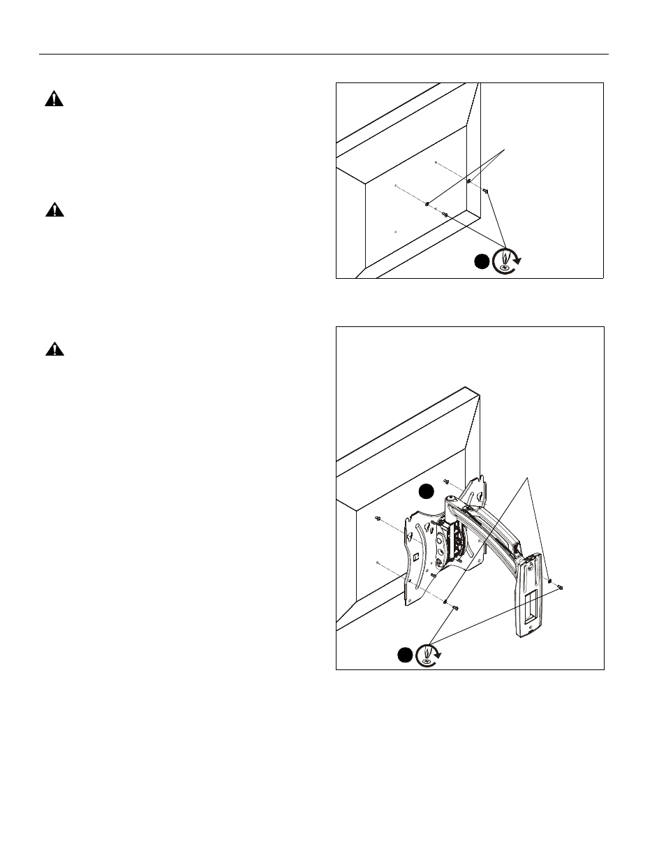
3.
Install two selected screws (A-C) into upper two holes on
back of display. (See Figure 7)
IMPORTANT ! : If using M4 or M5 screws (A or B),
washer hardware (D1 or D2) should be used to ensure
tight fit into the faceplate holes!
IMPORTANT ! : For recessed mounting holes or to gain
extra space, 1/4" spacers (D3) may be used in between
the back of the display and the faceplate. Multiple
spacers may be used on each screw if more space is
needed.
4.
Hang display by two screws onto faceplate through either
inner or outer teardrop mounting holes. (200x200 mounting
pattern shown) (See Figure 8)
5.
Install two selected screws (A-C) through selected washer
hardware (D1 or D2 if necessary), lower holes on faceplate
and into lower two holes on display. (See Figure 8)
IMPORTANT ! : For recessed mounting holes or to gain
extra space, 1/4" spacers (D3) may be used in between
the back of the display and the faceplate. Multiple
spacers may be used on each screw if additional space
is required.
6.
Tighten all hardware to ensure display is securely mounted.
Figure 7
Figure 8
(A-C) x 2
3
(D2) x 2 with (B)
(D1) x 2 with (A)
or
4
5
(A-C) x 2
(200 x 200 shown on TS110SU)
(D2) x 2 with (B)
(D1) x 2 with (A)
or