CHIEF CM2C40 User Manual
Page 3
Installation Instructions
CM2C40
3
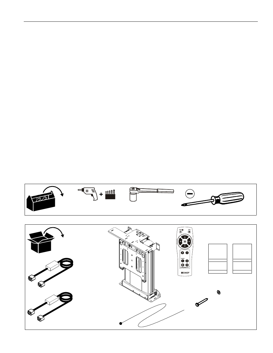
TOOLS REQUIRED FOR INSTALLATION
PARTS
CONTENTS
INSTALLATION REQUIREMENTS .............................................................................................................. 6
Power Requirements and Wiring ................................................................................................................ 6
INSTALLATION ............................................................................................................................................6
Pre-Installation Configuration and Adjustments ......................................................................................... 6
Configuring the Mount for the Display ..................................................................................................... 6
Cable Installation and Routing ................................................................................................................ 8
Mount Installation .................................................................................................................................... 11
Install Display ......................................................................................................................................... 12
Bottom Cover Installation ........................................................................................................................ 14
ADJUSTMENTS ............................................................................................................................................15
Bottom Cover Location Adjustment.............................................................................................................15
Lift Column Bearing Adjustment ................................................................................................................. 16
Extended Programming Capabilities ......................................................................................................... 17
IR-SE15 Programming ............................................................................................................................... 18
Serial Communications .............................................................................................................................. 19
CM2 Hardware Reference ...........................................................................................................................20
CM2 Interface Board Hardware Information ...............................................................................................20
Dry Contact Closures .............................................................................................................................. 20
Other Dry Contact Options ...................................................................................................................... 21
Connector and Switch Assignments ....................................................................................................... 23
5/16" x 2-1/2" x 10
x 1
(Europe)
x 1
x 1
O/I
I/M
x 1
x 1
x 1
5/16" x 10
x 1