2 wheel balancing 6.2.1 measuring unbalance, 2 correcting the unbalance, 3 recalculating unbalance values – CEMB USA K22 User Manual User Manual
Page 11: 4 automatic minimization of static unbalance, English
11
s
sx
x
g
g
g
g
d
dx
x
5
50
0°°
s
sx
x
g
g
g
g
d
dx
x
4
4 g
g
3
3 g
g
1
1 g
g
6
6 g
g
s
sx
x
g
g
g
g
d
dx
x
s
sx
x
g
g
g
g
d
dx
x
s
sx
x
g
g
g
g
d
dx
x
Use and maintenance manual Rev. 12-2010
ENGLISH
6.2 WHEEL
BALANCING
6.2.1 Measuring unbalance
Move the front lever to the right bring
▪
ing the pulley into
contact with the tyre and press the run button on the side
holding the lever pushed in order to spin the wheel. If
used without motor, spin the wheel by hand respecting
the correct direction of rotation (anticlockwise).
Release the lever and the START key when the
▪
displays go off, the machine will then start making
measurements.
When the displays show the measurement values, brake
▪
the wheel by re-establishing contact with the pulley,
which is braked when the motor is off. Instruments 1
and 2 will keep the dynamic unbalance values in their
memories. When balancing for static, the value is
shown on display 1.
LEDs on displays 3 and 4 will indicate the correction
▪
position. If all the LEDs are alight, this means that
the correction weight should be applied to the vertical
apex. In static mode, both displays indicate the same
position
(static unbalance).
For small diameter wheels (scooters), launch always the
▪
wheel by hand in anticlockwise direction (see arrow).
Measurement always begins when the displays go off.
6.2.2 Correcting the unbalance
STATIC:
Apply two identical correction weights at the
highest point of the wheel, one on the inside
shoulder and the other on the outside shoul
der of the rim. Each weight is half the value
indicated by the display. If you make the
correction with lead wire, springs or clamps
applied to the spokes, divide it onto one, tow
or more spokes, according to the size of the
unbalance.
DYNAMIC:
Apply the adhesive weights to the shoulders of
the wheel rim in the positions indicated by the
display for each of the sides.
Correction of inner side
Correction of outer side
Digital readouts with LED ‘s 3 - 4 lit up indicate the correct
angular wheel position to mount the counterweights (12 o’clock
position). In the event of unbalance less than the selected
threshold value
0
is displayed in place of the unbalance
value , with
it is possible to read the values below the
selected threshold gr. by gr.
INFORMATION
In rare cases and in temperature conditions near 0°, the
wheel balancer automatically activates a special measuring
cycle involving two successive measurements.
During the unbalance measurement, the word “START”
reappears to indicate to the user to bring the wheel back
up to speed. The accuracy of the unbalance values and
the reliability of the wheel balancer remain unchanged.
6.3 RECALCULATING
UNBALANCE
VALUES
Set the new dimensions as described above.
▪
Press
▪
, without repeating the spin.
The new recalculated unbalance values will be
▪
displayed.
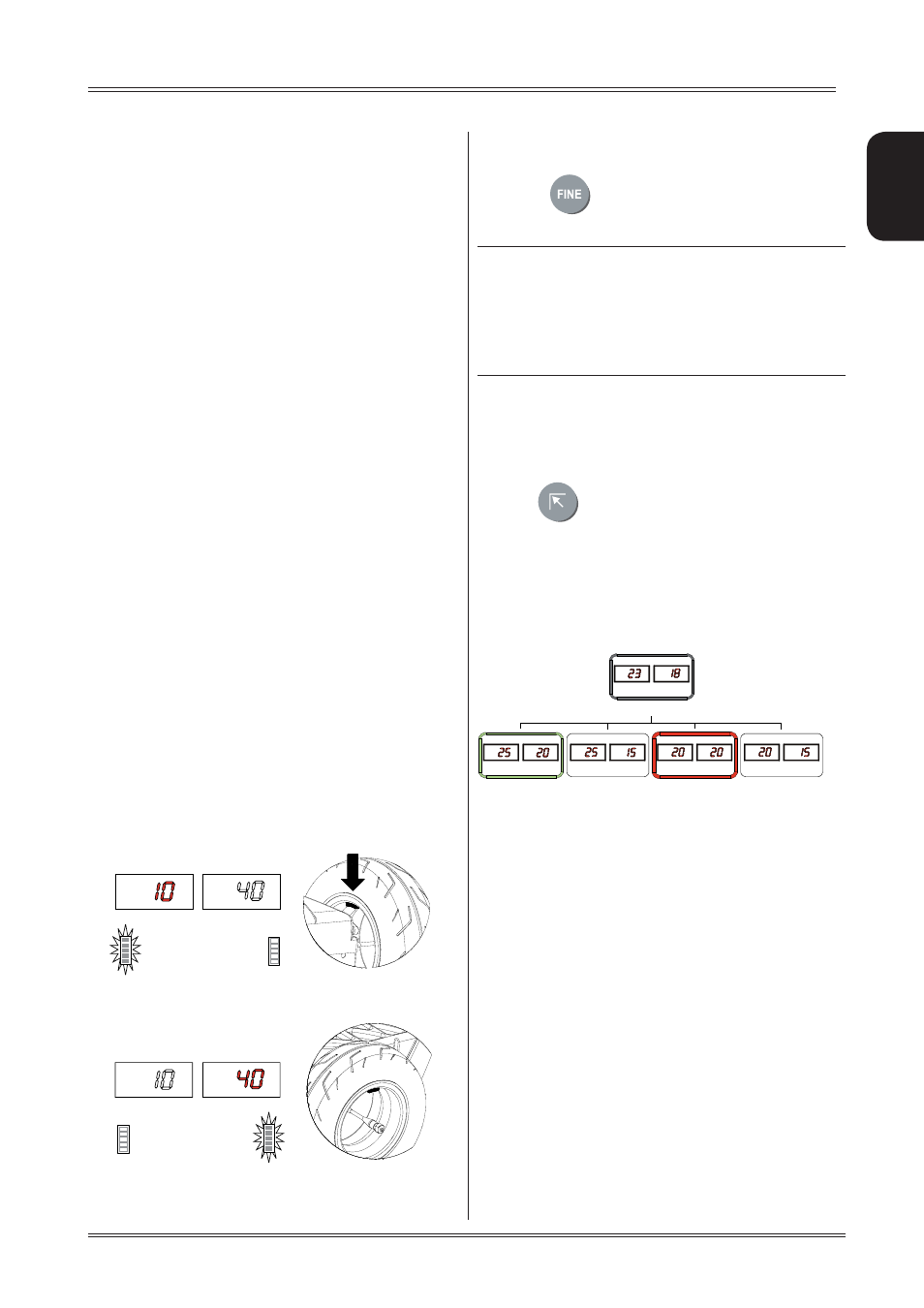
6.4
AUTOMATIC MINIMIZATION OF STATIC
UNBALANCE
This program is designed to improve the quality of ba-
lancing without any mental effort or loss of time by the
operator. In fact by using the normal commercially available
weights, with pitch of 5 in every 5 g, and by applying the
two counterweights which a conventional wheel balancer
rounds to the nearest value, there could be a residual static
unbalance of up to 4 g. The damage of such approximation
is emphasized by the fact that static unbalance is cause
of most of disturbances on the vehicle. This new function,
resident in the machine, automatically indicates the opti-
mum entity of the weights to be applied by approximating
them in an “intelligent” way according to their position in
order to minimize residual static unbalance.
Initial unbalance
Phase shift
Possible approximations
static residue
static residue
static residue
static residue
With traditional wheel
balancer
Choice with minimum static
unbalance
Use of the wheel balancer