API Delevan 2474 & 2474R User Manual
Series, Axial lead power inductors, Po w er i nd uc to rs
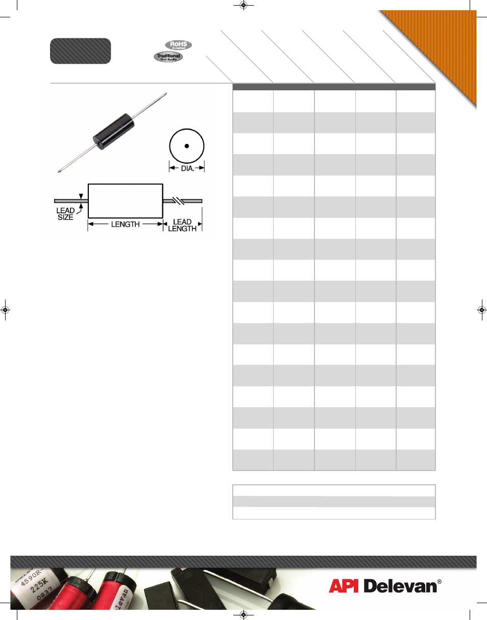
Actual Size
DA
SH
NU
MB
ER
*
IN
DU
CT
AN
CE
@
1 k
Hz
(µH
) ±1
5%
CU
RR
EN
T R
AT
IN
G
MA
XIM
UM
(A
MP
S)
IN
CR
EM
EN
TA
L
CU
RR
EN
T (A
MP
S)
DC
R
ES
IST
AN
CE
MA
XIM
UM
(O
HM
S)
SERIES
2474R
2474
Axial Lead Power Inductors
Mechanical Configuration Units are axial leaded for
thru-hole mounting, encapsulated in an epoxy molded
case. High resistivity ferrite core, allows for high inductance
with low DC resistance.
Physical Parameters
Inches Millimeters
Length 0.740 ± 0.010 18.80 ± 0.25
Diameter 0.240 ± 0.010 6.10 ± 0.25
Lead Size
AWG #20 TCW 0.032 ± 0.002 0.813 ± 0.051
Lead Length 1.44 ± 0.12 36.58 ± 3.05
Operating Temperature Range –55°C to +125°C
Current Rating 40°C Rise over 85°C Ambient
Maximum Power Dissipation at 85°C 0.50 W
Inductance Measured at 1 V with no DC current
Incremental Current The current at which the inductance
will be decreased by a maximum of 5% from its initial zero
DC value.
Weight Max. (Grams) 2.5
Marking DELEVAN; inductance with units and tolerance;
date code (YYWWL). Note: An R before the date code
indicates a RoHS component.
Example: 2474R-02K
Front:
Reverse:
DELEVAN 0902A
1.2uH±10%
Packaging Tape & reel: 12" reel, 1000 pieces max.; 14"
reel, 1500 pieces max. For additional packaging options,
see technical section.
Made in the U.S.A.
Po
w
er I
nd
uc
to
rs
270 Quaker Rd., East Aurora NY 14052 • Phone 716-652-3600 • Fax 716-652-4814 • E-mail: [email protected] • www.delevan.com
SERIES 2474 FERRITE CORE
-01L
-02L
-03L
-04L
-05L
-06L
-07L
-08L
-09L
-10L
-11L
-12L
-13L
-14L
-15L
-16L
-17L
-18L
-19L
-20L
-21L
-22L
-23L
-24L
-25L
-26L
-27L
-28L
-29L
-30L
-31L
-32L
-33L
-34L
-35L
-36L
-37L
-38L
-39L
-40L
-41L
-42L
-43L
-44L
-45L
-46L
-47L
-48L
-49L
-50L
-51L
-52L
6.4
5.8
5.2
4.8
4.3
3.9
3.5
3.2
2.9
2.7
2.5
2.2
2.0
1.8
1.6
1.5
1.4
1.2
1.1
1.0
0.93
0.85
0.77
0.71
0.64
0.58
0.52
0.48
0.43
0.39
0.35
0.32
0.29
0.27
0.25
0.22
0.20
0.18
0.16
0.15
0.14
0.12
0.11
0.10
0.09
0.09
0.08
0.07
0.06
0.06
0.05
0.05
6.27
5.95
5.67
5.43
5.22
5.03
4.70
4.56
4.01
3.84
3.69
3.55
3.27
3.09
2.97
2.84
2.66
2.25
2.17
2.05
1.84
1.65
1.56
1.53
1.30
1.12
1.04
0.99
0.84
0.80
0.74
0.68
0.59
0.56
0.49
0.42
0.39
0.37
0.34
0.30
0.28
0.25
0.23
0.20
0.19
0.18
0.15
0.13
0.12
0.12
0.10
0.09
1.0
1.2
1.5
1.8
2.2
2.7
3.3
3.9
4.7
5.6
6.8
8.2
10.0
12.0
15.0
18.0
22.0
27.0
33.0
39.0
47.0
56.0
68.0
82.0
100.0
120.0
150.0
180.0
220.0
270.0
330.0
390.0
470.0
560.0
680.0
820.0
1000.0
1200.0
1500.0
1800.0
2200.0
2700.0
3300.0
3900.0
4700.0
5600.0
6800.0
8200.0
10000.0
12000.0
15000.0
18000.0
0.009
0.010
0.011
0.012
0.013
0.014
0.016
0.017
0.022
0.024
0.026
0.028
0.033
0.037
0.040
0.044
0.050
0.070
0.075
0.084
0.104
0.130
0.145
0.152
0.208
0.283
0.330
0.362
0.505
0.557
0.650
0.770
1.03
1.14
1.50
1.98
2.30
2.55
3.00
4.00
4.40
5.80
6.56
8.63
10.1
11.2
15.0
20.8
23.4
26.0
36.0
40.0
Optional Tolerances: J = 5% H = 3% G = 2% F = 1%
*Complete part # must include series # PLUS the dash #
For surface finish information, refer to www.delevanfinishes.com
1/2009
API_newlayouts_single:APIcatalog_newlayouts 8/26/10 12:17 PM Page 94