API Delevan 4302 & 4302R User Manual
Series, Rf i nd uc to rs
Actual Size
SERIES
4302R
4302
SR
F M
IN
IM
UM
(M
Hz
)
DA
SH
NU
MB
ER
*
IN
DU
CT
AN
CE
(µ
H) ±
10%
Q M
IN
IM
UM
TE
ST
FR
EQ
UE
NC
Y (M
Hz
)
DC
R
ES
IST
AN
CE
MA
XIM
UM
(O
HM
S)
CU
RR
EN
T R
AT
IN
G
MA
XIM
UM
(m
A)
Temperature Stable for critical conditions
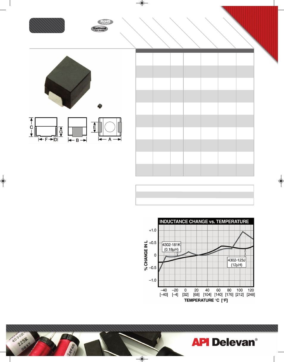
Physical Parameters
Inches Millimeters
A 0.095 to 0.115 2.41 to 2.92
B 0.085 to 0.105 2.16 to 2.66
C 0.075 to 0.095 1.91 to 2.41
D 0.010 to 0.030 0.26 to 0.76
E 0.040 to 0.060 1.02 to 1.52
F 0.060 (Ref. only) 1.52 (Ref. only)
G 0.045 (Ref. only) 1.14 (Ref. only)
Dimensions “A” and “C” are over terminals.
Weight Max. (Grams) 0.1
Operating Temperature Range –55°C to +125°C
Current Rating at 90°C Ambient 35°C Rise
Maximum Power Dissipation at 90°C 0.208 W
Note For applications requiring improved characteristics
over typical ferrite core inductors of the same size. See
1008 Series for values lower
than 0.12µH.
Marking SMD; dash number with tolerance letter; date
code (YYWWL). Note: An R before the date code indicates
a RoHS component.
Example: 4302-272K
SMD
272K
0422B
Packaging Tape & reel (8mm): 7" reel, 2000 pieces max.;
13" reel, 7000 pieces max.
Made In the U.S.A.
SERIES 4302 POWDERED IRON CORE
-121K
-151K
-181K
-221K
-271K
-331K
-391K
-471K
-561K
-681K
-821K
-102K
-122K
-152K
-182K
-222K
-272K
-332K
-392K
-472K
-562K
-682K
-822K
-103K
-123K
-153K
-183K
-223K
-273K
R
F I
nd
uc
to
rs
270 Quaker Rd., East Aurora NY 14052 • Phone 716-652-3600 • Fax 716-652-4814 • E-mail: [email protected] • www.delevan.com
Temperature Stable (1008 size)
Surface Mount Inductors
1075
1000
955
925
890
865
825
790
710
685
540
520
500
455
430
345
305
285
265
255
225
205
195
180
140
125
115
110
105
0.130
0.150
0.165
0.175
0.190
0.200
0.220
0.240
0.295
0.320
0.510
0.550
0.600
0.730
0.800
1.25
1.60
1.85
2.10
2.30
3.00
3.50
4.00
4.50
7.50
9.00
11.00
12.00
13.00
400
375
325
270
240
180
160
130
115
105
95
80
75
70
60
50
45
40
35
30
26
22
20
18
16
14
12
11
10
25.0
25.0
25.0
25.0
25.0
25.0
25.0
25.0
25.0
25.0
25.0
7.9
7.9
7.9
7.9
7.9
7.9
7.9
7.9
7.9
7.9
7.9
7.9
7.9
2.5
2.5
2.5
2.5
2.5
40
40
40
40
40
40
40
40
40
40
40
30
30
30
30
30
30
30
30
30
30
30
30
30
20
20
20
20
20
0.12
0.15
0.18
0.22
0.27
0.33
0.39
0.47
0.56
0.68
0.82
1.0
1.2
1.5
1.8
2.2
2.7
3.3
3.9
4.7
5.6
6.8
8.2
10.0
12.0
15.0
18.0
22.0
27.0
Optional Tolerances: J = 5% H = 3% G = 2% F = 1%
*Complete part # must include series # PLUS the dash #
For surface finish information, refer to www.delevanfinishes.com
For more detailed graphs, contact factory
1/2009
API_newlayouts_single:APIcatalog_newlayouts 8/27/10 3:14 PM Page 17