API Delevan 4448 & 4448R User Manual
Series, Po w er i nd uc to rs, Surface mount high current power toroids
Actual Size
0 A
MP
S D
C P
AR
AL
LE
L
IN
DU
CT
AN
CE
(µ
H)
TO
LE
RA
NC
E
DA
SH
NU
MB
ER
*
TO
LE
RA
NC
E
PA
RA
LL
EL
D
C R
ES
IST
.
MA
XIM
UM
(O
HM
S)
0 A
MP
S D
C S
ER
IES
IN
DU
CT
AN
CE
(µ
H)
RA
TE
D S
ER
IES
D
C
CU
RR
EN
T M
AX
IM
UM
(A
MP
S)
SE
RIE
S D
C R
ES
IST
AN
CE
MA
XIM
UM
(O
HM
S)
RA
TE
D P
AR
AL
LE
L D
C
CU
RR
EN
T M
AX
IM
UM
SERIES
4448R
4448
Surface Mount High Current Power Toroids
Test Methods Solderability per MIL-STD-202, Method 208.
Inductance tested at 10 kHz and zero Amp DC. Tested at 25°C
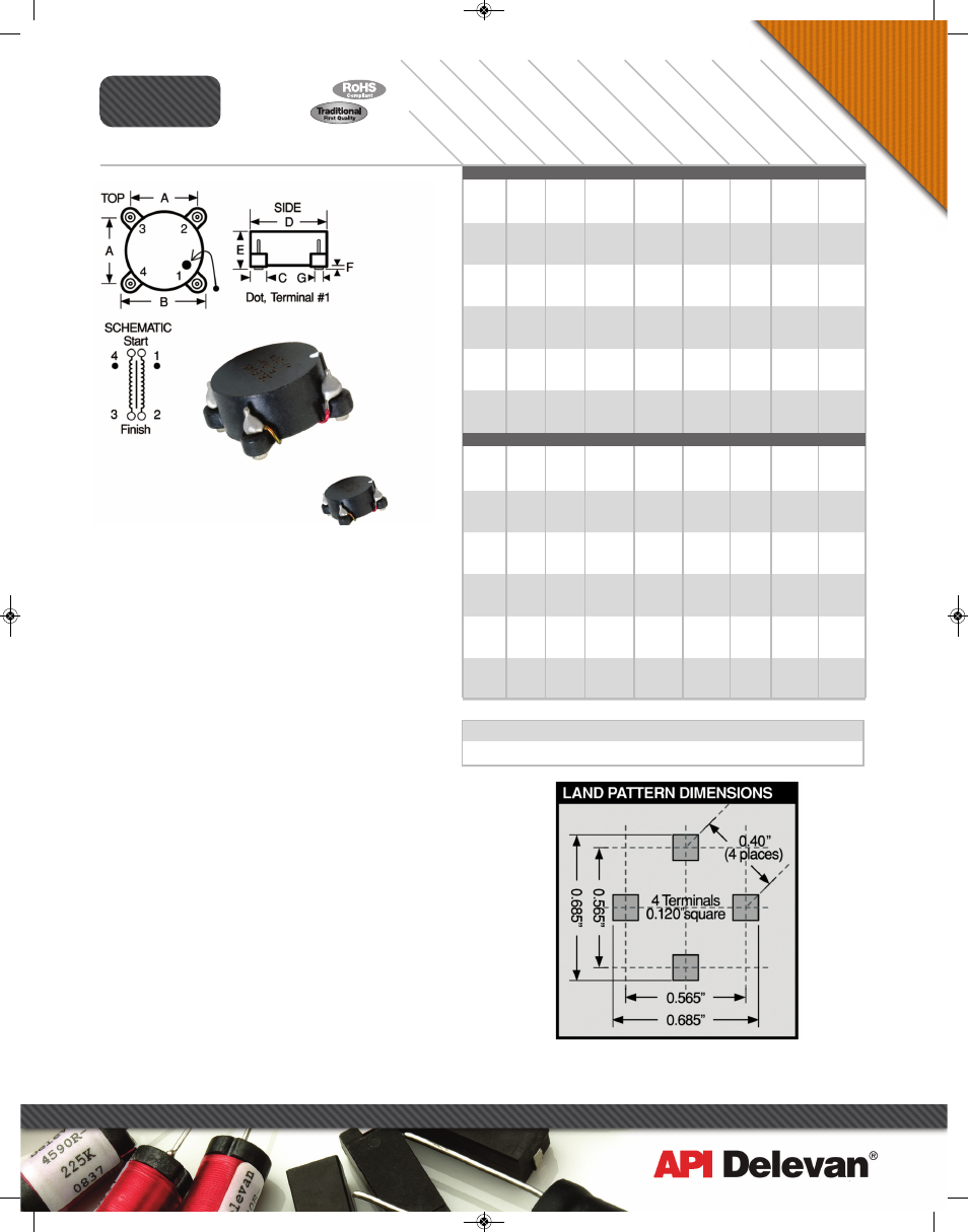
Mechanical Configuration A flat top surface mount case with
excellent coplanarity of terminals.
Physical Parameters
Inches Millimeters
A 0.390 to 0.410 9.91 to 10.41
B 0.520 to 0.540 13.21 to 13.71
C 0.115 to 0.135 2.92 to 3.43
D 0.480 to 0.500 12.19 to 12.70
E 0.310 Max. 7.87 Max.
F 0.020 to 0.040 0.51 to 1.02
G 0.060 (Ref. only) 1.52 (Ref. only)
Electrical Configuration Two inductors per unit;
internal terminals: #1(start) – #2(finish) &
#4(start) – #3 (finish).
Series Externally connect #2 to #4.
Parallel Externally connect #1 to # 4 and # 2 to # 3.
Operating Temperature Range –55°C to +125°C
Rated DC Current Based upon 20°C temperature rise from
25°C ambient.
Maximum Power Dissipation at 25°C 0.313 Watts
Inductance Tolerance Tolerance is specified by suffixing an
alpha character to the part number as follows: K = 10%, L =
15%. M = 20%. Units are normally supplied to the tolerance
indicated in the tables.
Marking Delevan; inductance and tolerance. A white dot
indicates the location of pin 1.
Example: 4448-102M
DELEVAN
.47uH±20%
Weight (Grams) 2.5 (Ref.)
Inductance at Rated DC Current Minimum percent of
measured zero Amp DC Inductance.
-02M to -34L = 60%; -102M to134L = 50%
Packaging Tape & reel (24mm):
13" reel, 350 pieces max.; 7" reel not available
Po
w
er I
nd
uc
to
rs
270 Quaker Rd., East Aurora NY 14052 • Phone 716-652-3600 • Fax 716-652-4814 • E-mail: [email protected] • www.delevan.com
SERIES 4448 POWDERED IRON CORE
-02M
-04M
-06M
-08M
-10M
-12M
-14L
-16L
-18L
-20L
-22L
-24L
-26L
-28L
-30L
-32L
-34L
SERIES 4448 FERROUS ALLOY CORE
-102M
-104M
-106M
-108M
-110M
-112M
-114L
-116L
-118L
-120L
-122L
-124L
-126L
-128L
-130L
-132L
-134L
3.95
3.60
2.95
2.30
1.65
1.50
1.25
1.15
0.95
0.80
0.65
0.60
0.55
0.36
0.32
0.30
0.27
3.95
3.50
3.25
2.95
2.20
1.75
1.70
1.50
1.05
1.00
0.90
0.75
0.60
0.46
0.41
0.32
0.31
0.020
0.024
0.036
0.056
0.108
0.132
0.188
0.228
0.340
0.464
0.664
0.808
0.952
2.260
2.784
3.240
4.012
0.016
0.020
0.024
0.028
0.056
0.076
0.080
0.096
0.220
0.254
0.288
0.444
0.632
1.212
1.488
2.180
2.688
± 20%
± 20%
± 20%
± 20%
± 20%
± 20%
± 15%
± 15%
± 15%
± 15%
± 15%
± 15%
± 15%
± 15%
± 15%
± 15%
± 15%
± 20%
± 20%
± 20%
± 20%
± 20%
± 20%
± 15%
± 15%
± 15%
± 15%
± 15%
± 15%
± 15%
± 15%
± 15%
± 15%
± 15%
2.00
3.00
4.00
8.00
20.0
32.0
40.0
60.0
80.0
100
132
200
272
400
600
800
1200
2.00
3.00
4.00
8.00
20.0
32.0
40.0
60.0
80.0
100
132
200
272
400
600
800
1200
0.005
0.006
0.009
0.014
0.027
0.033
0.047
0.057
0.085
0.116
0.166
0.202
0.238
0.565
0.696
0.810
1.003
0.004
0.005
0.006
0.007
0.014
0.019
0.020
0.024
0.055
0.064
0.072
0.111
0.158
0.303
0.372
0.545
0.672
7.90
7.20
5.90
4.60
3.30
3.00
2.50
2.30
1.90
1.60
1.30
1.20
1.10
0.72
0.64
0.60
0.54
7.90
7.00
6.50
5.90
4.40
3.50
3.40
3.00
2.10
2.00
1.80
1.50
1.20
0.92
0.82
0.64
0.62
± 20%
± 20%
± 20%
± 20%
± 20%
± 20%
± 15%
± 15%
± 15%
± 15%
± 15%
± 15%
± 15%
± 15%
± 15%
± 15%
± 15%
± 20%
± 20%
± 20%
± 20%
± 20%
± 20%
± 15%
± 15%
± 15%
± 15%
± 15%
± 15%
± 15%
± 15%
± 15%
± 15%
± 15%
0.47
0.68
1.00
2.00
5.00
8.00
10.0
15.0
20.0
25.0
33.0
50.0
68.0
100
150
200
300
0.47
0.68
1.00
2.00
5.00
8.00
10.0
15.0
20.0
25.0
33.0
50.0
68.0
100
150
200
300
*Complete part # must include series # PLUS the dash #
For surface finish information, refer to www.delevanfinishes.com
1/2009
API_newlayouts_single:APIcatalog_newlayouts 8/26/10 9:36 AM Page 76