Appendix b – mdc pinout and links, Mdc connector pinout, Motec mdc 13 appendices – MoTeC MDC User Manual
Page 15
MoTeC MDC
13
Appendices
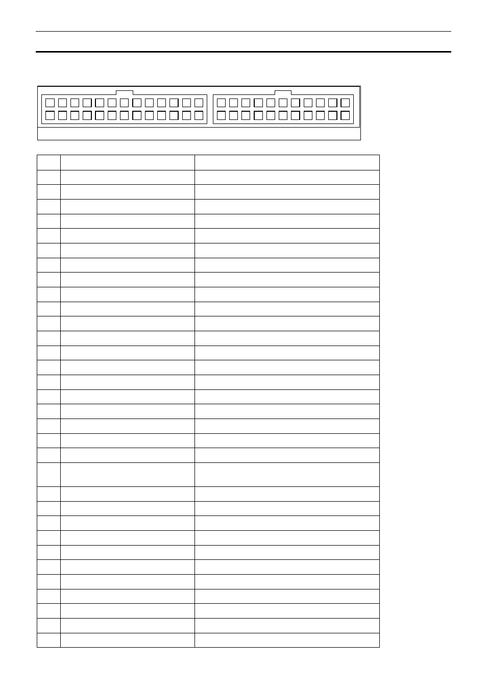
Appendix B – MDC Pinout and Links
MDC Connector Pinout
Plug C38
Plug C37
2
15
3
16
4
17
5
18
1
14
6
19
7
20
8
21
9
22
10
23
11
24
12
25
13
26
52
31 32 33
42
51
34
43
35
44
36
45
37
46
38
47
39
48
40
49
41
50
Pin
Function
Notes
1
ACD valve output
Switched positive output
6
Front left speed sensor input
Magnetic or Hall
7
Rear right speed sensor input
Magnetic or Hall
8
Rear left speed sensor input
Magnetic or Hall
9
Front right speed sensor input
Magnetic or Hall
10
0V
0V to hydraulic pressure sensor
11
Lateral G sensor input
13
Battery +
16
Pump relay output
Switched positive output
19
0V
0V to Front left speed sensor
20
0V
0V to Rear right speed sensor
21
0V
0V to Rear left speed sensor
22
0V
0V to Front right speed sensor
23
Longitudinal G sensor input
24
0V
0V to G sensors
26
Battery -
32
Hydraulic pressure sensor
33
Steering sensor P0 input
Rotary encoder phase 0
34
Steering sensor P1 input
Rotary encoder phase 1
36
ECU Comms
RS232 comms to MoTeC M800 OEM EVO89 or
EVO48
37
Handbrake input
0V when handbrake ON
38
Brake pedal input
12V when brakes applied
39
Throttle position sensor input
40
TARMAC light output
Active low
42
Battery -
43
5V Aux
44
Steering sensor N input
Rotary encoder index
47
Mode switch input
12V when pressed
48
ABS active input
0V when active
51
SNOW light output
Active low
52
GRAVEL light output
Active low