DE-STA-CO 600RGD/RGS User Manual
Page 7
4. SETTING CAM.
CAUTION: This mechanism is designed to operate
with adjacent followers in close contact along their
entire width with the surface of the cam during the
dwell period. Unless this condition is achieved by
proper installation, the mechanism will not transmit
its rated load, and furthermore, serious damage to
the cam and output shaft will occur.
A. Place the cam in dwell (keyway facing
rearward).
B. Rotate the tops of both input cartridges
toward the output until the cam followers
touch the cam.
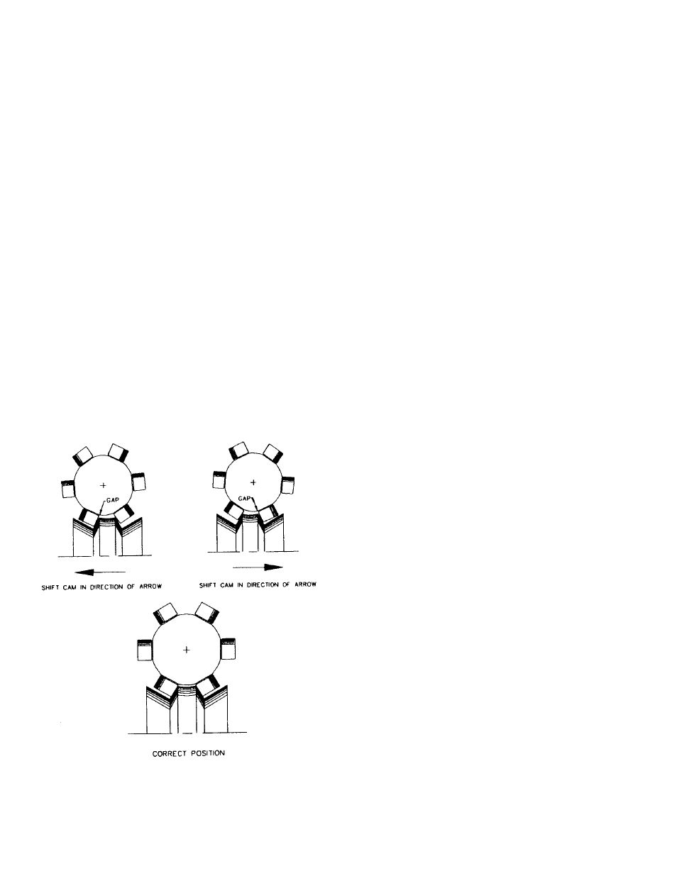
C. Shift the cam axially until two adjacent
followers are in full contact with the cam rib.
(This will also require adjustment of the
eccentric input cartridges along with axial
adjustment of the cam.)
1) If there is a gap at the root of the
follower the cam should be shifted
toward the follower.
2) If there is a gap at the tip of the follower
the cam should be shifted away from the
follower.
Fig.8 Centering cam
D. Apply “Prussian Blue” to entire cam track.
E. Rotate the camshaft slowly with a small
handcrank to ensure that:
1) Both rollers are in contact with the cam
rib in dwell. Look for uniform bluing
pattern.
2) The follower is free at the center of the
crossover track.
3) You do not encounter unusual
resistance in motion. The bluing pattern
should be fairly uniform from side to side
during motion. If a patch of bluing id
worn off the side of the cam rib on one
side of the cam and not the other, shift
the cam a .002 to .005 inches in the
direction of the worn side. Do not
overshift the cam or knocking will occur.
4) The cam bluing should never be worn
off the leading or exit edges of the cam
ribs. If so this is an indication that the
cam is not adjusted properly.
5) There should be no looseness in any
dwell. If there is adjust the eccentric
input cartridges to slightly preload the
loosest dwell.
F.
Tighten the locknuts and secure with Loctite
#242 as specified in the “General Service
Manual”. If lockwashers are used on your
model, bend the tangs over the nut to insure
locking.
G. Tighten the input cartridge capscrews and
dowel the cartridges to the housing.
H. Double check for endplay in output shaft.
Endplay is not permissible in the output
shaft.
5. Reinstall the access cover with a new
gasket. To insure leakage it is
recommended you also apply “General
Electric Silicone Rubber RTV-6” to the
housing and cover. CAUTION: If your
access cover is plexiglass be sure not to
over tighten or cracking will result.
6. Grease pack the main output bearing
with lubricant specified in the “General
Service Manual”.
7. Install new oil seals as described in the
“General Service Manual”.
8. Fill the index with the recommended oil
to level indicator. See “General Service
Manual”. Too high an oil level will cause
no damage. Too low a level may result in
unit failure.
6