Assembly prior to reassembly – DE-STA-CO 600RGD/RGS User Manual
Page 5
7. Check the follower holes for roundness. These
holes may be worn out due to overloads. The
holes should be round within .0005 to permit
reuse of the follower wheel.
8. REMOVAL OF BEARINGS.
A. Remove the large output bearing cone from
the output shaft with a small diameter
aluminum bar and a hammer. Place the bar
against the protruding edge of the cone and
tap with the hammer, working around the
perimeter to prevent binding. Continue this
until the cone is free of the shaft.
Fig.4 Removing bearing cone.
B. Remove the output bearing cups from the
cartridges and housing with puller, by prying
or by drilling and tapping for jack screws.
9. INPUT SHAFT / CAM REMOVAL.
NOTE: The output shaft must be removed prior to input
shaft removal.
A. Rotate the input shaft and inspect all parts
for wear or damage. Endplay in the input
shaft is not permissible.
B. Match mark all input cartridges relative to
the housing. These must be reinstalled in
the same side and position since they are
eccentric.
C. Remove all input bearing cartridge
capscrews.
D. Tap on the end of the input shaft to drive the
opposite cartridge from the housing. Then
drive the shaft in the opposite direction for
removal of other cartridge.
NOTE: Keep shims with their respective cartridges. You
will be asked to reinstall or replace with same shim
thickness during assembly.
E. Use a wheel puller to remove the bearing
cones from the input shaft.
F.
Remove the cam locknuts with a spanner
wrench, if applicable. Be sure to bend the
washer locking tang away from the nut prior
to removal.
G. Press the shaft through the hole previously
occupied by the input cartridge (removed in
Step D). This will automatically remove the
cam from the input shaft. The use of an
arbor press is recommended but this
procedure can be accomplished by driving
the shaft through with a soft faced hammer.
Fig. 5 Pressing out shaft.
H. Remove cam through the access opening.
10. Remove the input bearing cups from the
cartridges with a pulley puller, by prying or by
drilling and tapping for jack screws.
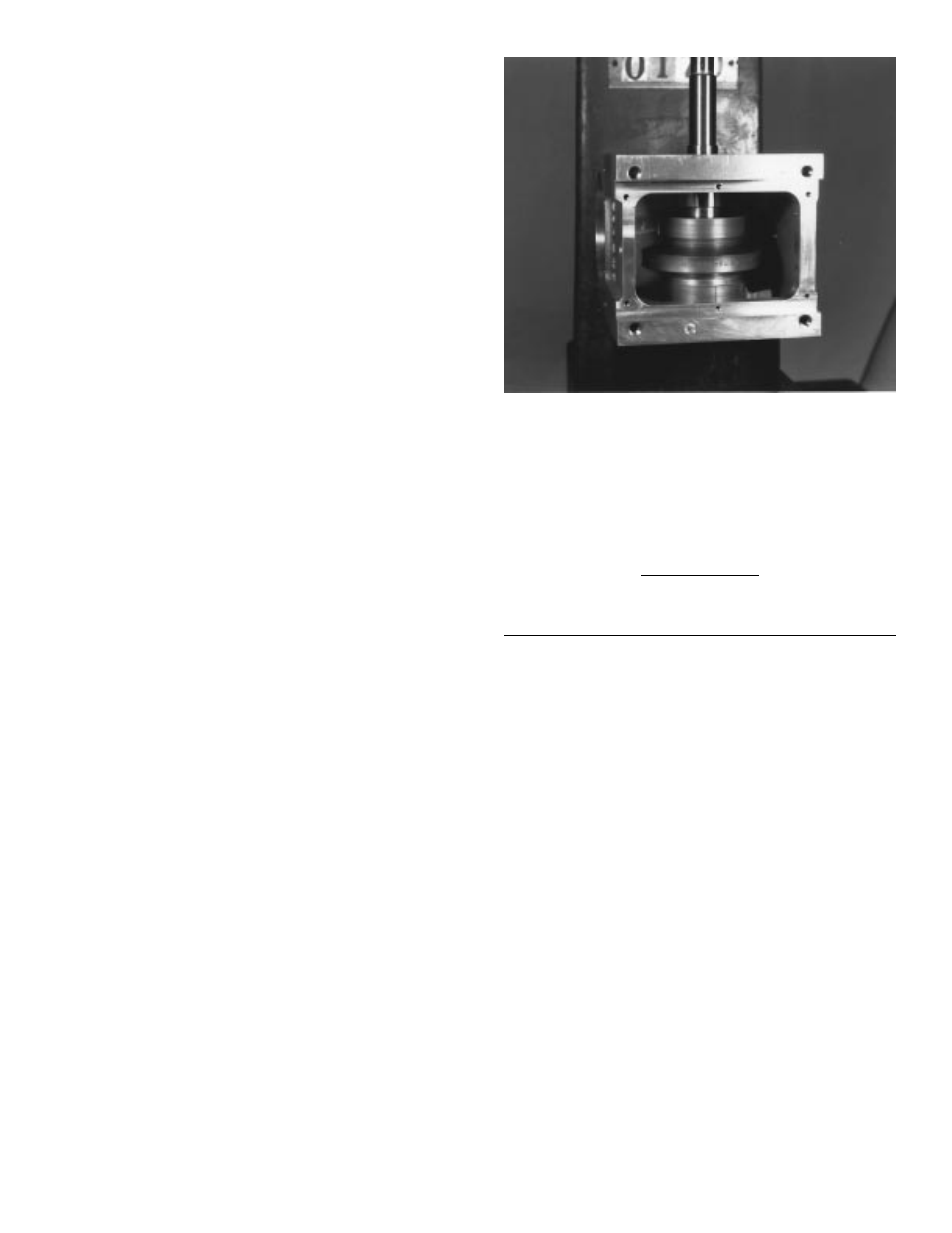
ASSEMBLY
PRIOR TO REASSEMBLY
Clean and deburr all parts before reassembling
Follow tightening torque and Loctite™
recommendations as outlined in the “General
Service Manual”.
1. Use an arbor to press the bearing cups into the
cartridges. Coat the outside of the cup and the
bore of the cartridge with an anti-seize lubricant
prior to pressing. Fill cavity of cartridges with
bearing grease recommended in the “General
Service Manual”.
2. ASSEMBLING INPUT SHAFT.
NOTE: Assembly of the cam and bearings to the input
shaft must be done inside the housing.
A. Use arbor to press the cam onto shaft. Be
sure key is installed into shaft first. Apply
anti-sieze lubricant to shaft and bore prior to
pressing. The bore of the cam should be
heated prior to pressing, if a heat gun is
available.
B. Use a spanner wrench to install the cam
locknuts. Adjust nuts to center cam on shaft
( if applicable).
4