DE-STA-CO 1800RDM User Manual
Page 8
E. Apply “Prussian Blue” to entire cam track.
F.
Rotate the camshaft slowly with a small
handcrank to ensure that:
1) Both rollers are in contact with the cam
rib in dwell. Look for uniform blueing
pattern.
2) The follower is free when it is in the
center of the crossover track.
3) You do not encounter unusual
resistance in motion. The bluing pattern
should be fairly uniform from side to side
during motion. If a patch of bluing is
worn off the outside of the cam rib on
one side of the cam and not the other,
shift the cam a .002 to .005 inches in the
direction of the worn side. Do not
overshift the cam or knocking will occur.
4) The cam bluing should never be worn
off the lead-in or exit edges of the cam
ribs. This would indicate that the cam is
not adjusted properly.
5) There should be no looseness in any
dwell. If there is looseness adjust the
output bearing retainer to slightly
preload the loosest dwell.
G. Tighten the locknuts and secure with
Loc-Tite #242 as specified in the “General
Service Manual”. If lockwashers are used on
your model, bend the tangs over the nut to
insure locking.
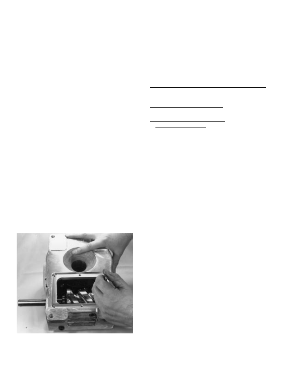
Figure 10 Tighten cam locknuts
H. Tighten the output retaining ring capscrews.
I.
Drill and ream the remaining hole in the
output retaining ring to accept the next
larger dowel pin. Install new dowel.
8. REINSTALL THE BOTTOM COVER. Apply
“General Electric Silicone Rubber RTV-6” to the
sealing surfaces of the housing and cover. Place
the gasket on the housing and place cover over
the gasket. Install and tighten capscrews.
9. GREASE PACK THE MAIN OUTPUT BEARING
with lubricant specified in the “General Service
Manual”.
10. INSTALL NEW OIL SEALS as described in
the “General Service Manual”.
11. FILL THE INDEX WITH THE
RECOMMENDED OIL to level indicator. See
“General Service Manual”. Too high an oil level
will cause no damage. Too low a level may result
in unit failure.
7