Measuring methods, Specifications – B&K Precision 309 - Manual User Manual
Page 7
-5-
-4-
5.MEASURING METHODS
BEFORE PROCEEDING WITH MEASUREMENT,
READ THE SAFETY NOTES ON PAGE 2.
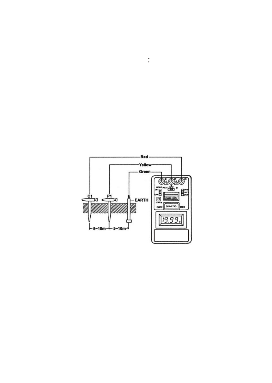
1. Connection with test leads
Connect green, yellow and red test leads to instru-
Ment terminals E, P and C with auxiliary earth bars
P1, C1 driven into earth "IN A STRAIGHT LINE".
(Fig.1)
2. Set the function switch to ACV position and make
certain that the voltage reading is LESS THAN
10V AC, otherwise accurate earth resistance
measurement may not be made.
3. Set the Range Switch to suitable range and set the
function switch to W position then press the PUSH-
ON BUTTON and TIMER ON BUTTON at the same
time and take the reading on the display.
ê When none of E, P and C terminals connected
with test leads, the display shows "1" at W function.
ê Follow the proper connection such as Fig. 1, the
LED(red) indicator will lit. This proves a correct
current circulation is under its operation.
4.SPECIFICATIONS
Measurement system
Earth resistance by constant
Current inverter. 820Hz, 2mA
approx.
Earth voltage
0~200Vac, 40~500Hz.
Earth resistance range and resolution
0~20W (0.01W).
0~200W (0.1W).
0~2000W(1W).
Accuracy
Earth voltage ± (1%rdg+2dgt)
Earth resistance ± (2%rdg+2dgt)
or ± 0.1W, which is greater.
Safety standard
IEC 1010-1 (EN61010-1) CAT III
200V.
Low battery indication
"B" symbol appears on the
display.
Data hold indication
"DH" symbol appears on the
display.
Over range indication
"1" (MSD).
Timer (auto power off)
About 3~6 minutes.
Display
LCD 3½ digit (2000 counts).
Power source
1.5V(R6P)*6 pieces dry batteries.
Dimensions
163(L)*100(W)*50(D)mm.
Wight
Approx. 410g (battery included).
Accessories
Test leads (Red-15m,yellow-10m,
green-5m), Auxiliary earth bars,
Heavy case, Instruction manual.